Dance Platform Firmware
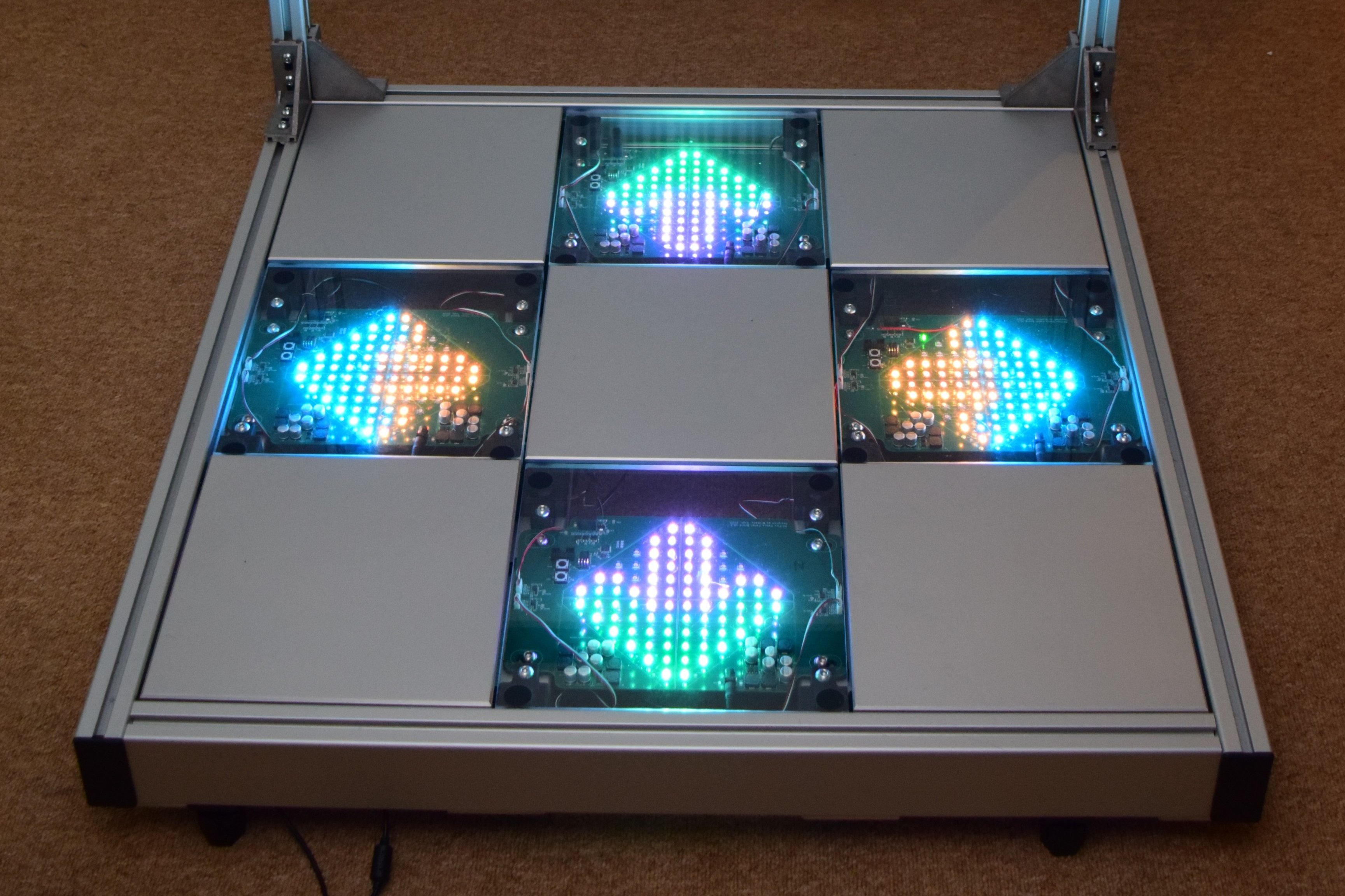
The RE:Flex dance platform is a modern take on the concept with precise sensors and 84 RGB LEDs per panel.
My fiancée designed a dance platform (much like those you see in arcades) from the ground up, albeit with more modern technology. After getting the basic proof of concept working, she enlisted my help to get the 5 microcontrollers and USB connection working together reliably.
Sensor System
The dance platform features 4 playable panels (arrows) with 4 load cells each. Those load cells, much like in electronic scales, measured the mass on them, and present a tiny voltage change for it. This small voltage is then amplified to a usable range, and measured by an analog to digital converter (ADC) built in to an STM32F3-series microcontroller.
The readings of each panel’s 4 sensors get periodically requested by the IO board, through a UART connection over RS-485. On the IO board, these readings get collected and reported back to a PC via USB.
Lighting System
Meanwhile, the PC sends out 24-bit RGB data for each LED across the 4 player panels. A full frame, that is the collection of RGB data for all the LEDs, is sent in several USB packets. The IO board reads a header byte in each packet to see which panel board it’s addressed to and sends it on via UART.
On the panel board side, the data is processed into a format ready for clocking out to the LEDs. Once all the data of a frame has been received and processed, the IO board sends a message telling the panel boards to output the new LED data. This data has to be clocked out according to the LEDs’ timing specification; it’s done with a combination of a timer peripheral, direct memory access (DMA) requests, and a GPIO port. Through this method, data for 4 lines of 21 LEDs each is clocked out simultaneously. All this happens achieving a frame rate of 50~60 frames per second.
Work Involved
- Organisation of existing firmware code for easier maintenance
- Design of a state-management system for the IO board’s UART communication, including managing one of the microcontroller’s UART peripherals being shared between two physical ports
- Optimisations to LED processing code
- Debugging of state / timing issues in UART comms and LED one-wire output with logic analyser
- Integration of tinyUSB library (replacing a less efficient one provided by ST)
- Memory safety fixes to several parts of existing firmware
- Implementation of extensive “unit test” suite, allowing easy testing of individual parts
- Refactoring of some Python code on the PC-side, allowing PNG files to be easily displayed on LEDs
More Images
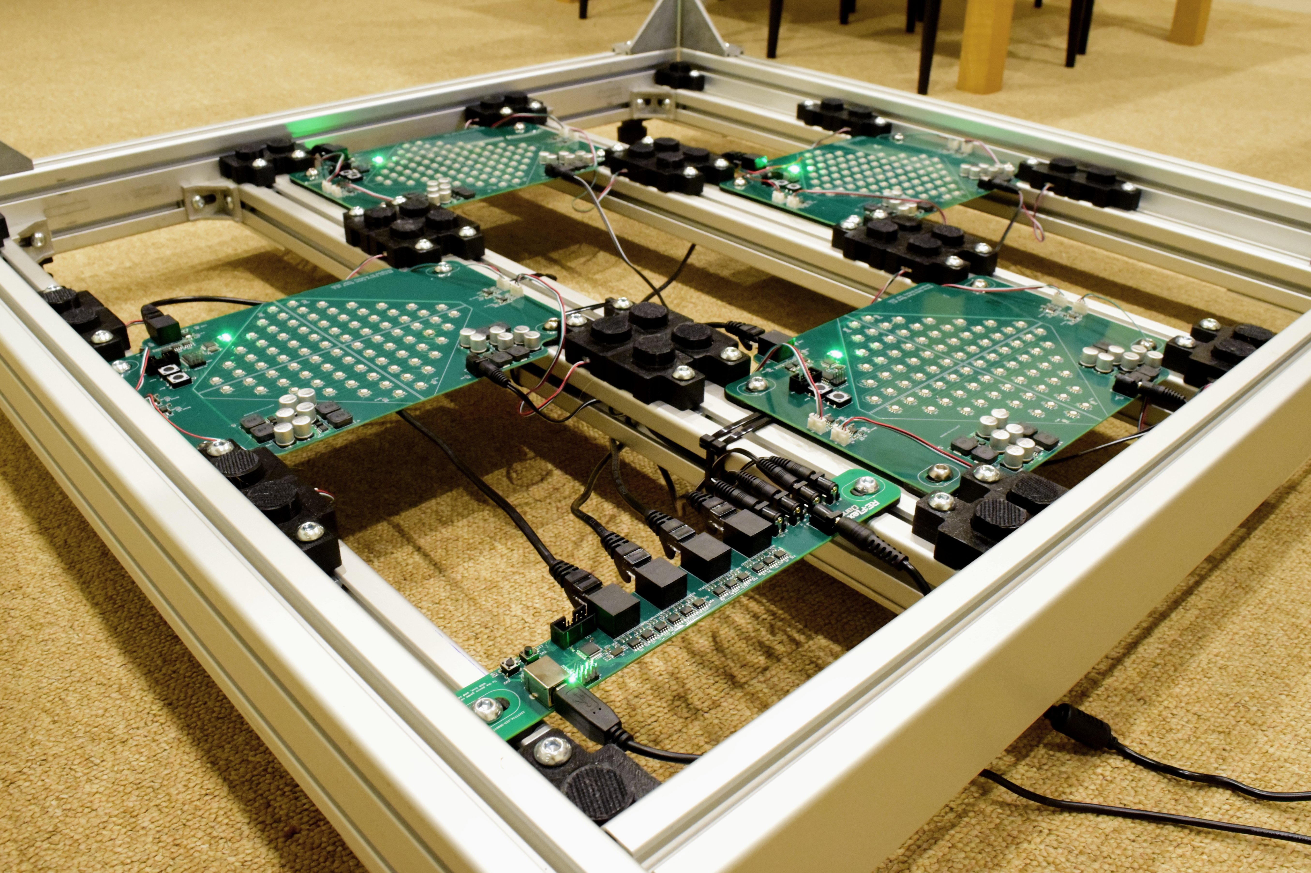
A lower angle closer look. The board nearest the camera is the IO board. It connects to a computer via USB, and to all 4 panel boards using RJ-45 connectors. Further there are some distribution barrell jacks for supplying power. The black parts bolted into the framework contain the sensors, while others are standoffs for non-playable panels.
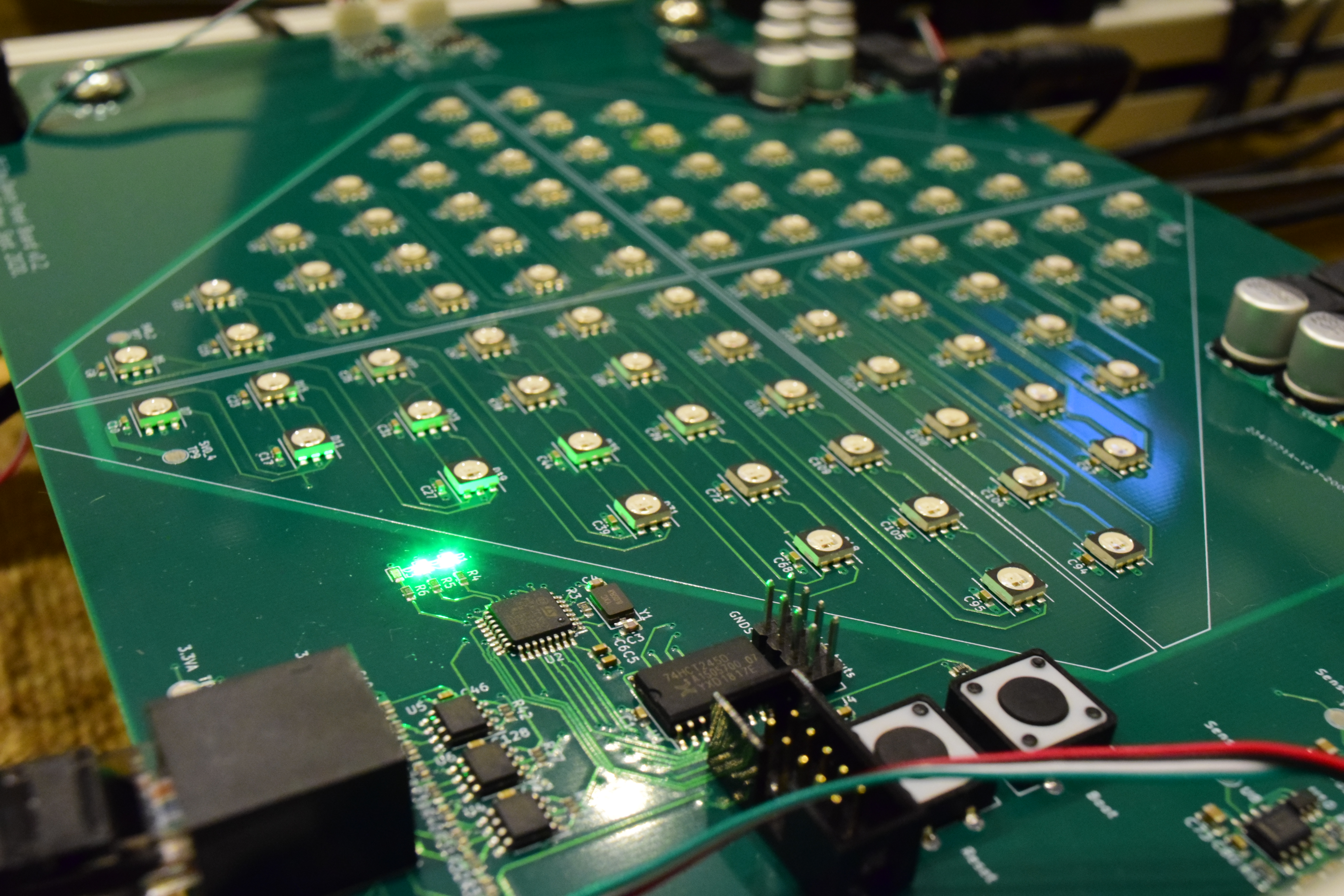
Close-up of a panel board. The 3 ICs nearest the connector in the bottom left are RS-485 transceivers. The large one between connectors is a voltage level shifter, and the small one near the small green LEDs is the STM32F3-series microcontroller. In the background are switching mode power supplies for the LEDs.
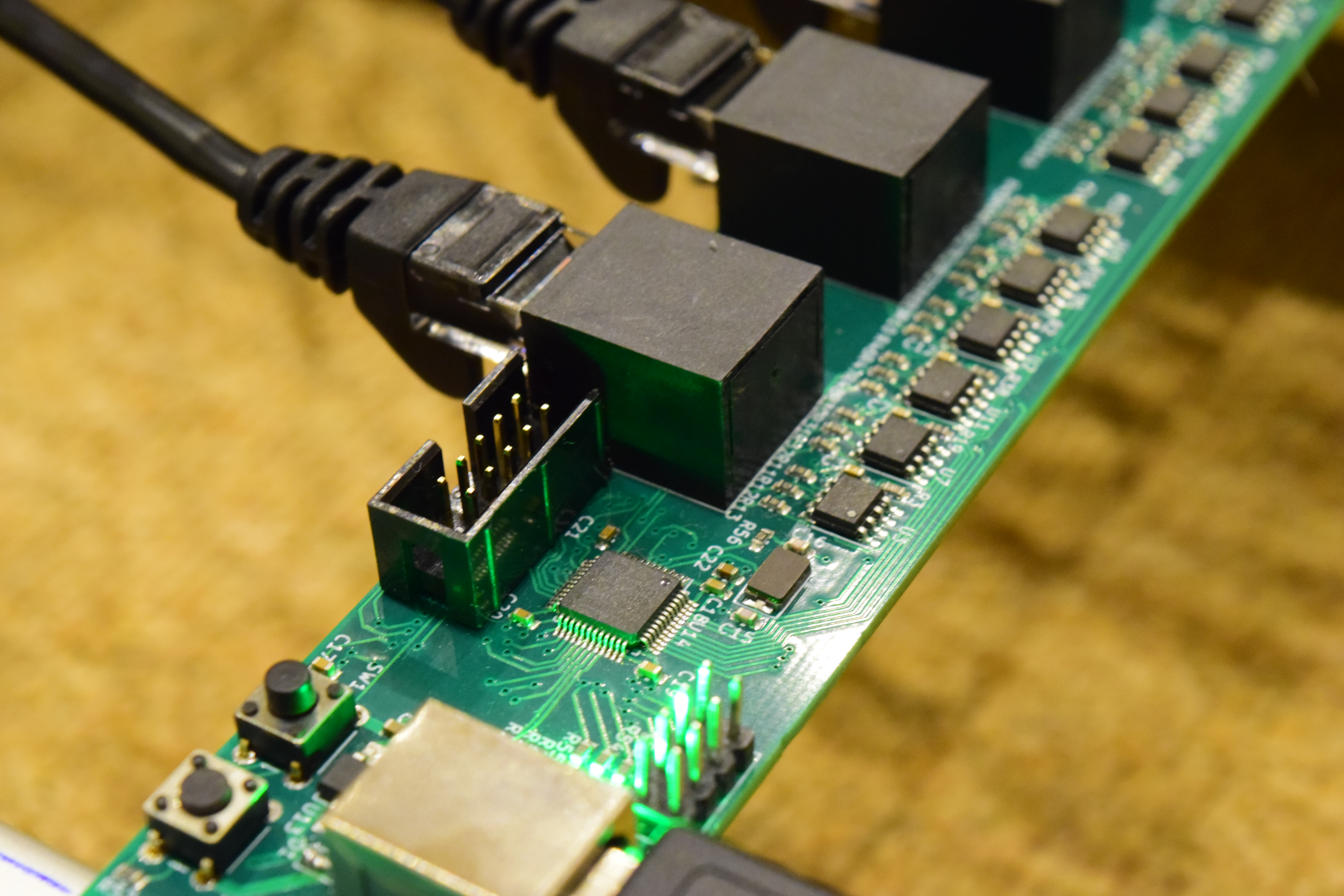
Close-up of IO board, focusing on the microcontroller. Like on the panel boards, this is also an STM32F3-series microcontroller, but this model features a higher pin count and USB connectivity, as required here.
As of 2020-12-12, you can find all the design files and code of this whole project through reflex.dance (Site by yours truly).
More specifically, the firmware I worked on is here: