Yearproject: FPGA MIDI synth
Over the past two years, I’ve completed a bachelor course in electronics. In the second and thus final year, we were assigned to come up with a project to complete over the year. My classmate Raf and I are both interested in music production, so we decided it would be a fun idea to create our very own synthesizer.
We actually made the decision to make a synthesizer in our first year, so we certainly would have enough time to work it all out properly. In this first year, we were introduced to the FPGA, which can briefly be described as a digital playground that allows you to build just about any digital circuit on it. (To give an idea: You could actually design a micro-controller on the thing if you’d want to).
Our interest for the FPGA sparked, we decided to use that to build the synthesizer around. Thus the decision was made to go digital. Anyway, I could go on for a while on the why and when, but let’s take a look at how this stuff works first.
Clarifying some terms
The name of the project is made up of 2 acronyms and an abbreviation, so let’s have a look at what all these mean.
FPGA stands for “Field Programmable Gate Array”. This name basically speaks for itself: it is an array of programmable gates, which we can program “on the field”. It is system, presented as an integrated circuit, which can be reprogrammed as many times as you want, using a generic computer. We’re using the Xilinx Spartan 3E for our project, for a pretty simple reason: The school has a bunch of educational Digilent Nexys 2 boards lying around, so it was easiest to just work with what was available.
NOTE 2016-07-10: There were link here for both the Xilinx Spartan 3E FPGA and the Digilent Nexus 2 board, but neither of them were up anymore, so I’ve removed them.
MIDI stands for “Musical Instrument Digital Interface”. It is basically a protocol designed for transferring musical information to and from digital instruments and controllers. It is sent of a serial line, in a way similar to RS232. MIDI information is sent in messages of 3 byte.
Byte 1, the status byte describes what is happening. This can be the act of pressing a key, releasing a key, moving the pitch bend wheel, or what have you. Each possible action has its code. Our synthesizer just listens for “key pressed” and “key released” codes.
Byte 2, ‘data 1′, represents any extra data to go with the action presented in the first byte. In our case, that is which note is being pressed or released. Be it A3 or C4 or whatnot, it’s in this byte.
Byte 3, ‘data 3′ hold any more information. In the case of pressing a key, this one holds the ‘velocity’, which is nothing more than how hard you pressed the key down. When you’re releasing a key, this holds the ‘aftertouch’, which is the exact opposite, namely how quickly you allowed the key to come back up. In our synthesizer, we ignored this one for simplicity.
There’s a bit more to it, but this was the essential part for explaining the synthesizer.
Synth is short for synthesizer. A synthesizer is as you all probably know nothing more than an electronic device that electrical signals that with the aid of a speaker form sound of different frequencies, mostly meant for music.
How it’s done
MIDI input
For our MIDI input, we used a laptop and a MIDI interface, namely the CakeWalk UM-2G. Another option would be to simply attach a MIDI keyboard, but we found the MIDI interface in combination with some software worked best to experiment and demonstrate.
MIDI filter
The MIDI filter is a simple circuit from the MIDI specification, which essentially filters out noise and voltage peaks. The most important part is the opto-coupler in this circuit. Having an optical barrier between the MIDI input and the FPGA also protects the FPGA a bit more. We designed a little PCB for this part, which you can see in the photos section at the end of the article.
FPGA
This is where the magic happens. The FPGA interprets the MIDI information and generates the audio we want. We decided to use the Wavetable principle for our synthesizer, on which I’ll elaborate further in the post. The FPGA takes in the serial MIDI signal, and sends out audio with a resolution of 8 bits. The sampling rate of the output varies as it’s dependant on the pitch, but that’ll be clarified with the explanation on the wavetable as well.
DAC (Digital to Analog Converter)
This, as the name implies, takes our digital signal and converts it to an analogue voltage. The DAC uses an R/2R ladder for the conversion, and 2 generic 741 op-amps to amplify to voltage and remove the DC offset. It is powered by a symmetric power supply, which is a rather simple circuit built around the 7812 and 7912 voltage regulators. We’ve designed and made the PCBs for both the DAC and its power supply, and they can be seen in the photo section as well.
Amp + speaker
Now we’ve got an analogue signal, we want it to be audible as well, thus, we amplify it a bit and output it through a speaker. The focus of the project was mostly on interpreting the MIDI and generation the audio signal, so we used a cheap kit for the amplifier.
The Wavetable principle
I’m not going to lie; the wavetable principle is actually a very simple synthesizing method, but interesting nonetheless.
A sine wave can be represented quite easily, with a simple formule: v = sin(t). Now, that’s all fine and dandy if you want a sine wave, but once you want to create a multitude of waveforms, the formulae will get more complex. Added to that is that it provides no usable way to add waveforms without really having to dive into the code.
The solution to that is using tables that represent that waveforms; it allows us to store any possible waveform in the same way.
Basically, what we do is take a sine or any other wave form, and take a sample of the current value at short time intervals. This sample is nothing more than number, which is then added as a row in our table/list. We decided to divide our waveforms in 256 samples. This means we get a list of 256 numbers, which quite accurately describe our waveform. (We’re using a precision of 8 bits, as mentioned earlier).
Now for the opposite: if we have such a wavetable, how do we turn this into sound again? The answer is simple: We run over all of the values in the list and output them to the DAC. The DAC converts the individual values to analog voltages, which, outputted in rapid succession, creates our waveform.
If we want to play this waveform at different pitches, all we have to do is change the speed with which we run over our table.
FPGA
Let’s dive into how everything was done in the FPGA now.
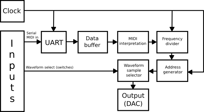
That’s a slightly more complex schematic that the overview one, but let’s get into it. We’ll just follow the way the signal goes from MIDI in to audio out.
We start at “Serial MIDI in”. This is where our signal comes in from the MIDI filter we’ve seen earlier. This serial signal is fed to the UART, (which stands for Universal Asynchronous Receiver/Transmitter). What it does in our case is basically split the serial data stream into individual bytes, and feed them to Data buffer. It’s quite a bit more complex than that (with start and stop bits and proper synchronising etcetera), but to be frank, I don’t remember the specifics very well any more. What matters is that the UART outputs a byte at a time and that it lets the data buffer know when there is a new byte available.
Data buffer simply stores 3 bytes. Whenever a byte is available at its input, it’s shifted in. The reason for 3 bytes specifically is probably already clear; it’s because a MIDI message consists of 3 bytes. Data buffer makes the latest 3 bytes available to the MIDI interpretation element simultaneously, so it can properly be interpreted.
MIDI interpretation then keeps an eye out for a “Note on” or “Note off” status byte. It remembers whether or not a note is currently playing with these. Furthermore, this element reads the data 1 byte to know which note to play. It passes on the “Note ON/OFF” information as well as this note ‘name’ information to the frequency divider.
Frequency divider divides the clock frequency (50MHz) by a number that results in the right pitch. This element outputs a new clock signal, at our resulting frequency, to the address generator.
Address generator is an 8-bit counter. As mentioned, out waveforms are built up of 256 samples. Each of these samples has their own number, ranging from 0 to 255. These numbers can be referred to as addresses, since the wavetables can be seen as simple pieces of memory, with values stored in locations that all have their address. Anyway: frequency divider determines the speed at which this counter runs.
Waveform sample selector is what’s left. This element contains our wavetables, one for each waveform. Using some on-board switches, we can choose between sine, triangle, saw, saw-square and square. Address generator provides this block with the current address; sample selector locates the sample at that address in the selected table, and outputs it to the DAC.
Output (DAC), last but not least, converts our digital signal to the analogue signal, and sends it the amplifier, which sends it to the speaker. And that my friends, is how we’ve gone from a serial MIDI signal to an audible tone.
Photos
Obviously this wouldn’t be complete without an idea of what this whole mess looks like. Here’s a set of photos. You can click them to see the full size.
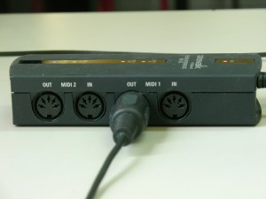
The MIDI interface
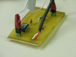
The little MIDI filter circuit
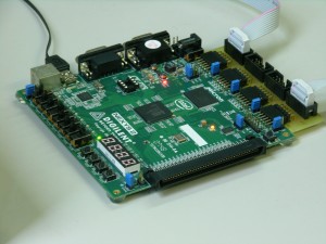
Digilent Nexys 2 FPGA board with a handy connector PCB
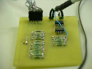
The Digital to Analog Converter (DAC)
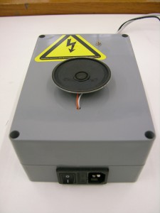
Our grey box, which hold the DAC power supply, the audio amplifier, and the speaker on top.
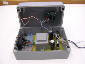
The inside of our grey box. On bottom there is the DAC power supply, and the little PCB on top is the audio amplifier.
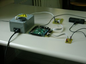
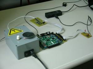
The whole setup
Video demonstration (on Youtube)
That about rounds it up; thanks for reading. If you have any questions or general comments, don’t hesitate to post them!
