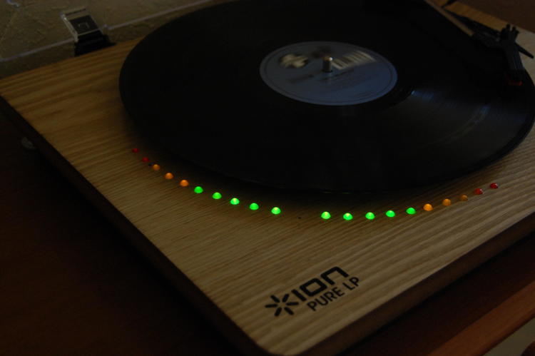
Adding stereo VU meters to a turntable
My fiancée got me a great gift for my last birthday: a turntable. Being a classic trance lover, I’ve since been collecting a bunch of records. The thing has really been a source of joy thus far.
About a month ago I started itching to do a little electronics project again as it had been a while. Long story short, I figured it’d be neat to open up this relatively simple device and add a nice aesthetic feature to it: VU meters.
Since this is a rather involved hack, (as opposed to my line-in addition to a boombox), it gave me a good reason to finally check out Southampton’s maker/hackerspace, SoMakeIt.
First steps: prototyping
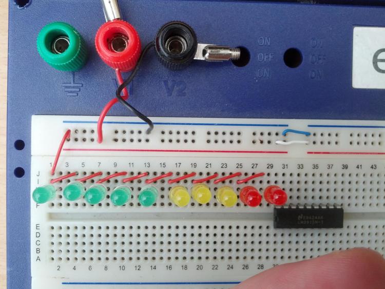
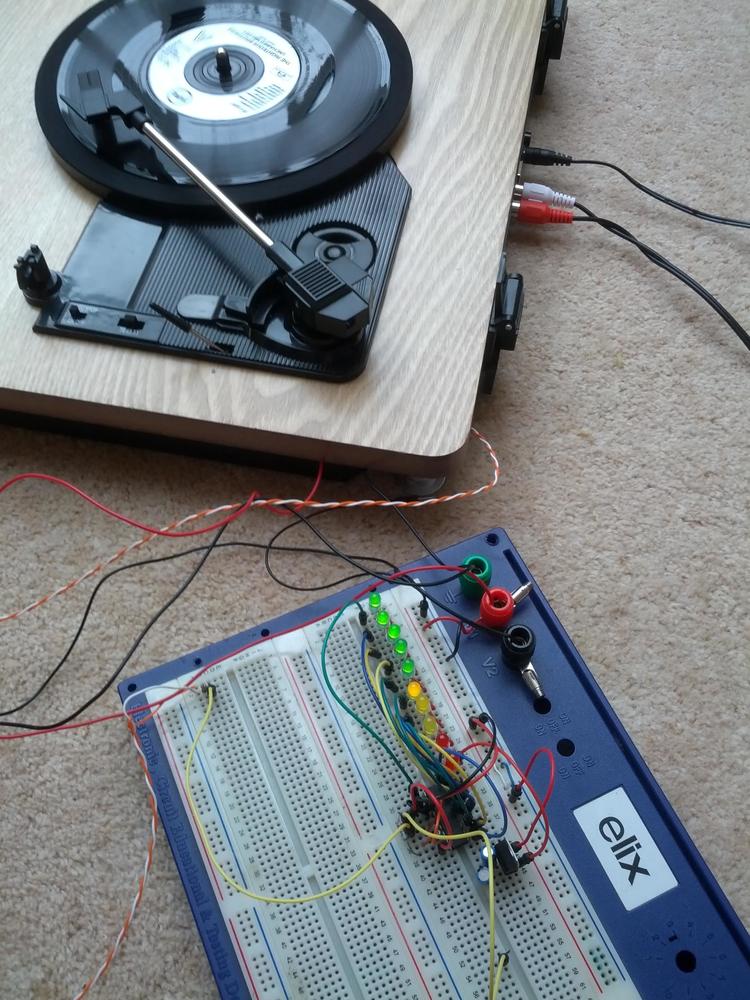
As with any fun electronics project, it started on a breadboard. I happened to have an LM3915 (PDF) (Dot/bar display driver) laying around, which makes building the basic circuit pretty straightforward. The datasheet linked provides the necessary circuit, which I built on my breadboard.
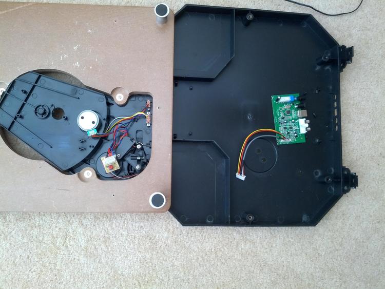
After a quick test to confirm the circuit worked with an mp3 player as audio source, I opened up the turntable to figure out how I could wire up my additions to the existing circuitry. On one of the circuit boards, I found a few free holes, which happened to be connected to the power supply. It’s almost as if this thing was designed to be hackable.
The audio signal was a little bit more tricky to wire up. I ended up soldering it to the RCA out connectors.
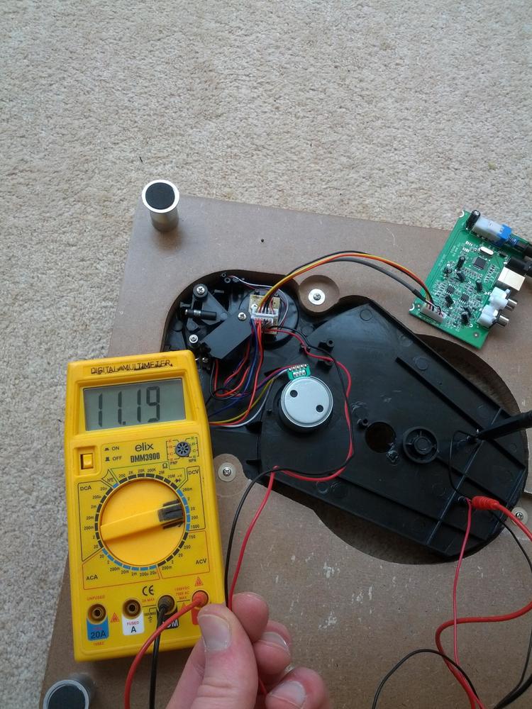
My next step was to test whether my prototype would still work using the power supply and audio signal from the turntable. Reading through the LM3915 datasheet, I found that my 11.2V was a little over the maximum of 7 Volts for powering the LEDs. Luckily, I had a few of those trusty old 7805 Voltage regulators lying around, so I put together the classic voltage regulator circuit, bringing the LED voltage source down to 5 Volts.
After this progress, I took a break from the project as I was going to see family in Belgium. When I got back, I immediately arranged to go check out SoMakeIt, where I could further work on implementing this project. Turns out they have a lot of awesome kit, and, more importantly, a bunch of very welcoming, friendly people. I’m happy to report I’m now a member. If you’re from the Southampton area, I highly recommend checking it out.
At the first opportunity, I took my laptop in and worked on a schematic. I talked to some people about the project, and got some new ideas. Bracken gave me the idea to add a sort of peak indicator to it.
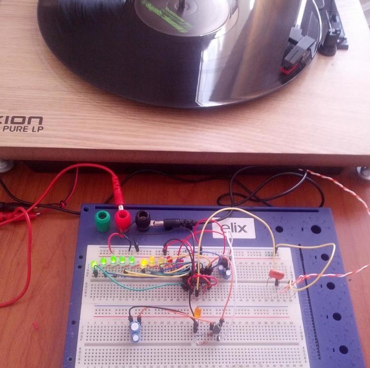
I accomplished this by wiring the 10th LED through a transistor, which in turn powered an LED, but also charged a capacitor. This way, when the 10th LED gets turned on and off again, it fades out for a little while, distinguishing it from the other LEDs.
Back at home, I observed that many of my records would give me a full bar of lit LEDs most of the time, due to audio compression and the loudness war. To combat this and add some dynamic to the visual output, I added a passive high pass filter (capacitor and resistor) to the signal input. Filtering out most of the bass got rid of a good deal of the constant loudness, making the LED bar interesting to look at again.
Putting it in more solid form
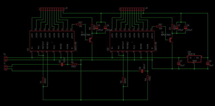
At this point, I had figured out exactly what I wanted from the circuit and figured out some variables to make it work optimally. Putting it all together, I drew this schematic in Eagle:
You can find this schematic file on the GitHub repository, turntable-vu-meters.
When I first visited SoMakeIt, someone was working on a PCB. Knowing that the space had the kit to develop PCBs in-house, I quickly decided I’d design a proper PCB, rather than build it on protoboard.
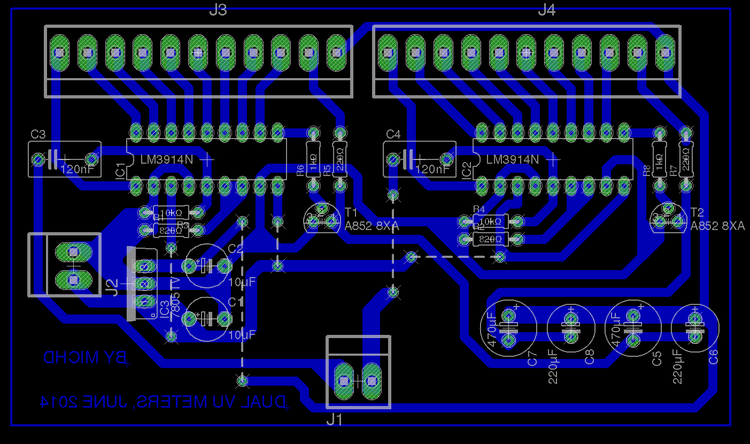
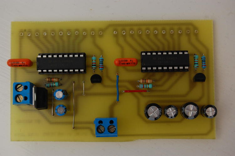
I got a little bit lazy with the PCB design, so there are 5 so-called “0 ohm resistors” (wire bridges) on there.
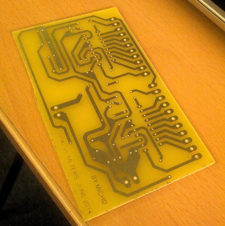
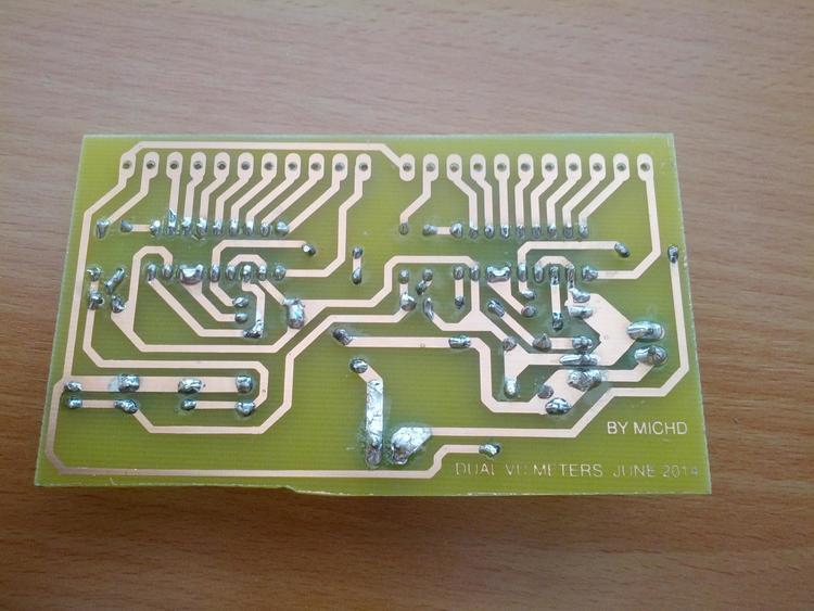
Behold:
This pcb layout file is also available on the GitHub repository.
I gave developing this PCB a go on my own on a Saturday, using some copper board I found at the space and cleaned up with some sandpaper, but failed pretty miserably. Turns out, if you’re going to use the UV lightbox method, you should first coat your blank PCB with a UV-sensitive layer. Who would have guessed‽
Anyway, I later went ahead and ordered some proper blank PCB with a UV-sensitive layer on there, and used that next time.
The next Tuesday, I got a lot of assistance from Dave in developing and etching the PCB. I say assistance, but in reality he did most of that work. Thanks Dave! :-)
The etch came out pretty well, with only some of the insignificant lettering having faded a bit.
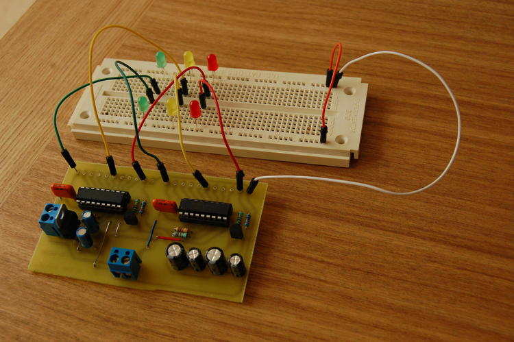
Now that the PCB was finished, I of course had to test it, for all I knew, I could’ve made an unnoticed mistake in the PCB design, or even in the schematic. For both channels, I wired up 3 of the LEDs, adding a tiny drop of temporary solder to keep the pins in place.
(Very) luckily, this worked perfectly; being a software developer by day, this surprised me.
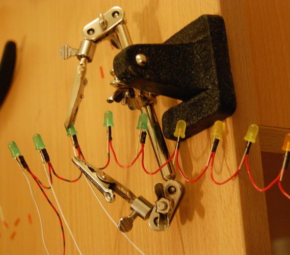
Knowing that the PCB was all done, I got to the fun part: soldering wires onto the LEDs, so that they’d fit in their designated holes on the turntable. I started by connecting all the anodes with short strands of red wire, a fun exercise in trimming and stripping.
I twisted the stripped ends together, and then added a little bit of solder on this joint. After completing a chain like this, I soldered the anode of an LED to each joint, ensuring I’d have a bit of heat shrink ready first.
After making a connection, I moved the heatshrink over the connection and shrunk it by rubbing it with the soldering iron. This worked out very well for insulating the anodes.
Once all the anodes were hooked up, I soldered a wire onto each cathode:
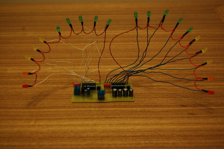
3 hours later, all the LEDs were wired up properly, including the connections to the PCB. It didn’t look very impressive in this form:
Into the turntable
After all that, a final step remained: mounting the LEDs into the wooden base of the turntable. I managed to cram the entire turntable in my backpack to take it to SoMakeIt, where I drilled the 20 holes along the diameter of a 12 inch record.
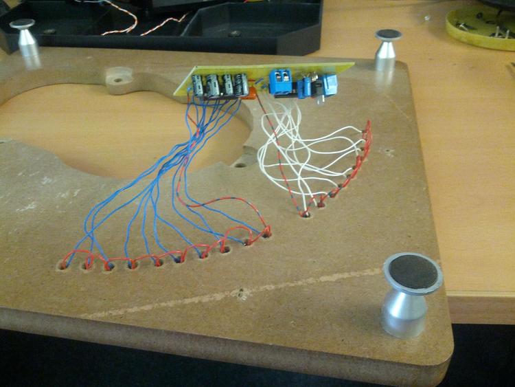
I enlarged the holes slightly by abusing my screwdriver, but after that, the LEDs actually fit in, nice and snugly.
It appears I left ample headroom in my common anode wiring, something I was quite glad about.
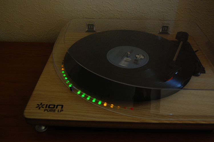
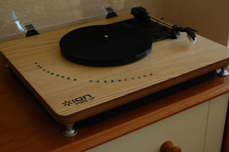
After putting everything back together and erasing my pencil guidelines, this was the final result:
As a bonus, a short video of the turntable playing Veracocha – Carte Blance. The audio is rather bad because phones just aren’t made for that kind of recording. Also, my choice of song for this demonstration wasn’t the best here, this is a particularly over-compressed song, resulting in all LEDs being on most of the time.
This was definitely a fun project to undertake, and I now enjoy listening to vinyl even more. In fact, I got distracted by it several times while working on this write-up.
