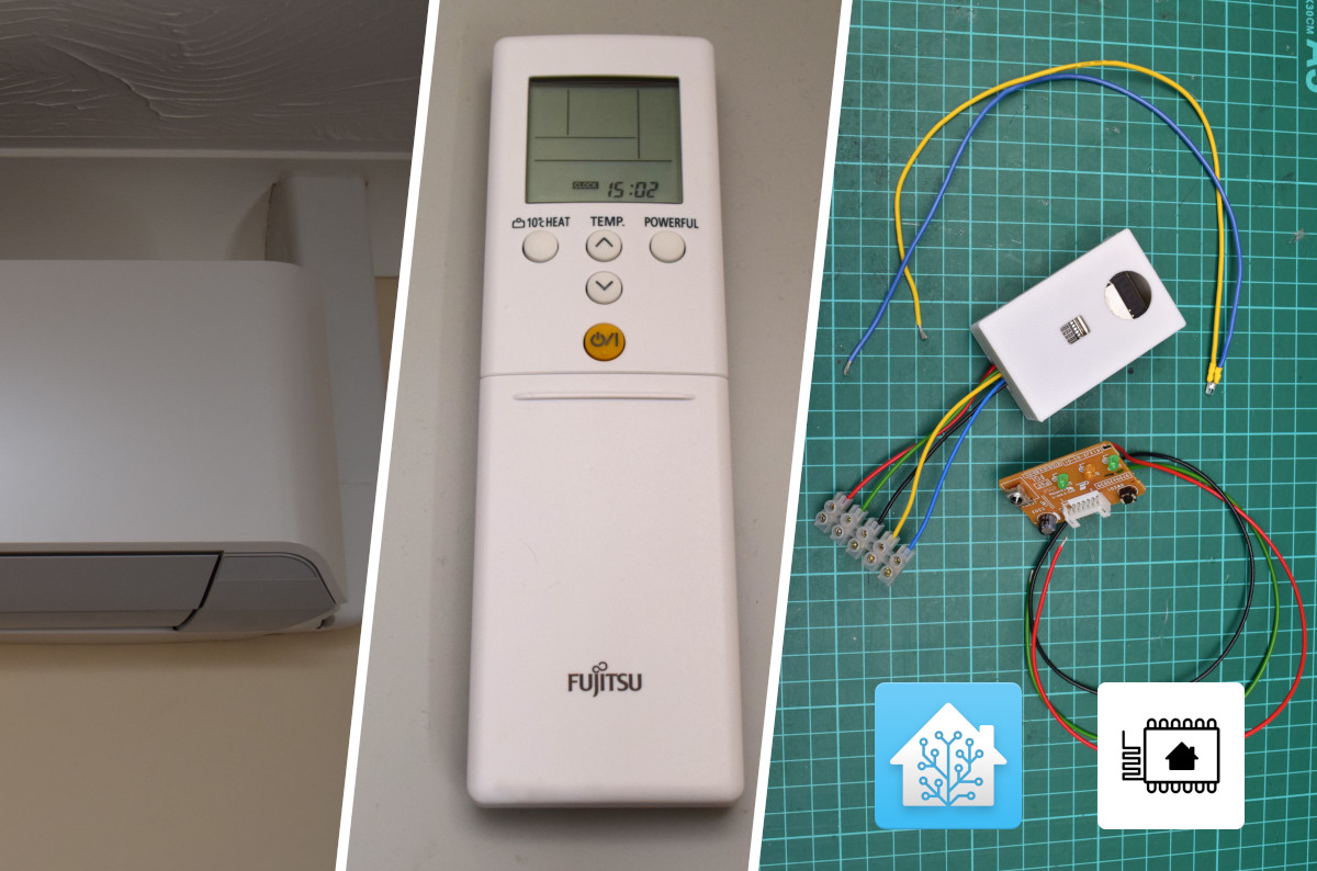
Integrating our Air Conditioners into Home Assistant
I added Home Assistant control to our air conditioner units. It involved PCB design, some 3D printing, equipment modification, and ESPHome.
Last year, we got an air conditioning system installed. Soon after, I got interested in home automation, but since we had cheaped out and didn’t get any “smart” control for the units, I had some DIY fun.
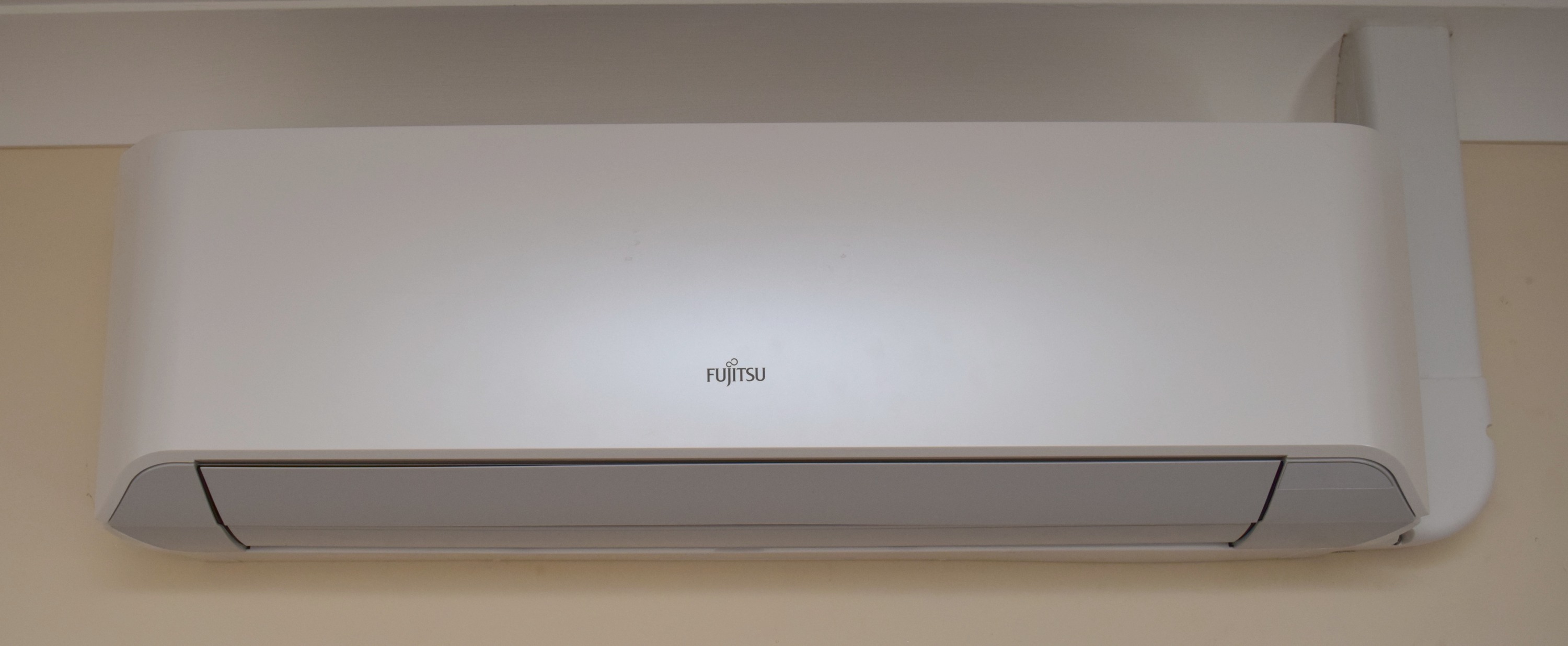
The air conditioner units we have indoors are the Fujitsu General’s ASYG07LMCE and the virtually identical but more powerful ASYG12LMCE. We only have the handheld infrared (IR) remote controls.
Not long after we had these installed, I set up Home Assistant for some other things, and have been controlling and automating with it ever since. The folks who make Home Assistant also make ESPHome, a system designed to employ the popular Espressif ESP32 and related WiFi-connected microcontrollers in home automation. ESPHome works with a wide range of electronic components, without having to do any of the firmware engineering.
I won’t go in depth about Home Assistant and ESPHome here, but suffice to say they’re tools that make home automation without the spying eyes of companies possible. They provide a tremendous amount of flexibility for the enthusiast.
ESPHome has community-provided options for talking to IR controlled devices, and, as it happens, even knows how to talk to Fujitsu General air conditioning units. This meant that I could skip the whole reverse-engineering of the remote control protocol, and instead write a few lines in a configuration file and go to town.
Building some hardware to use with ESPHome
ESP32 development boards are thankfully very easy to get a hold off. I’ve gone with (probably a knock-off of) the NodeMCU-ESP32 board for everything I’ve used an ESP32 in so far. I designed a simple board in KiCad that you plug one of these into.
The requirement for this board were:
- Allow controlling more than one device
- Send and receive IR; Receive, so that normal remotes can be used, and our system can pick up on it too
- Be flexible in case I want to wire up additional hardware later (reducing the need for a new board design)
The board I designed allows 3 IR LEDs, an IR receiver, and comes with additional pads for each of the ESP32 board’s pins.
You can find the designs and fabrication files on GitHub: michd/esphome-ir-box. It was designed with KiCad 7.

The first version, REV.0, contains one pin-out mistake on the IR receiver, which I’ve bodged around by insulating one of the leads and crossing it under the other. This mistake is corrected in REV.1. The IR LED has long insulated legs so it can be bent to point at the target device.
This particular board is for a room with just one device to control, so I only soldered on a single LED and its supporting components.
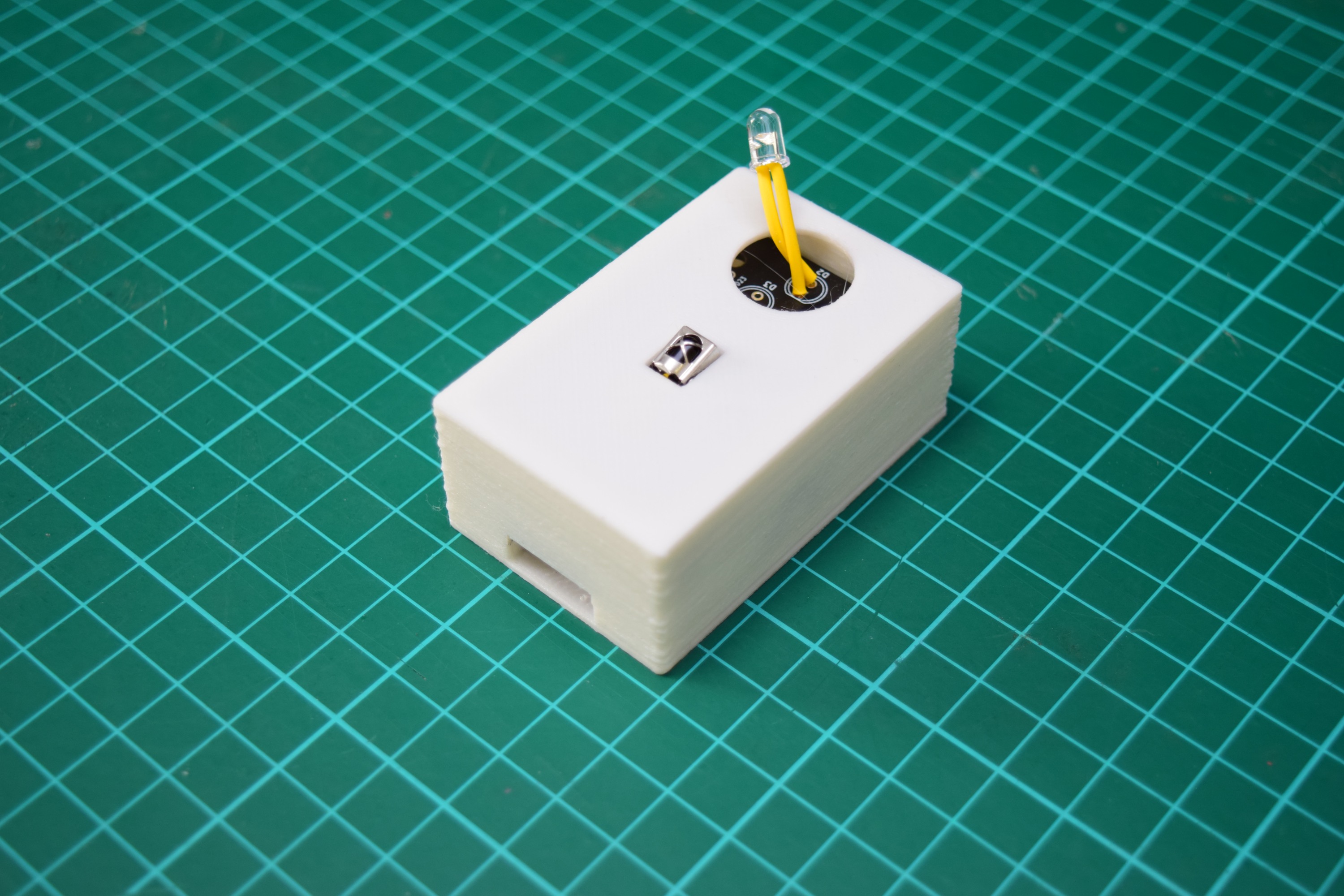
And here it is boxed up. I put these boxes near the A/C units, powered from a USB wall socket, set everything up in Home Assistant, and it worked great. While functionally great, it was an eyesore: a random box with a USB cable stuck to the wall, not to mention the bare components sticking out. My partner expressed the hope this setup was temporary and suggested it could be more integrated, so that’s what I investigated next.
Integrating into the A/C units
Disclaimer: I don’t know if I need to state it, but any risk to your equipment, your personal safety, your warranties, etc is entirely yours; I take no responsibility for your actions.
To get a look inside the A/C unit, I first turned off the breaker powering our A/C system. I then removed the cover and set it aside. I consulted the Installation manual’s section 9.1: “Front Panel removal” and followed the steps. (I highly expect this link will die at some point, but I don’t think I have the rights to republish the document).
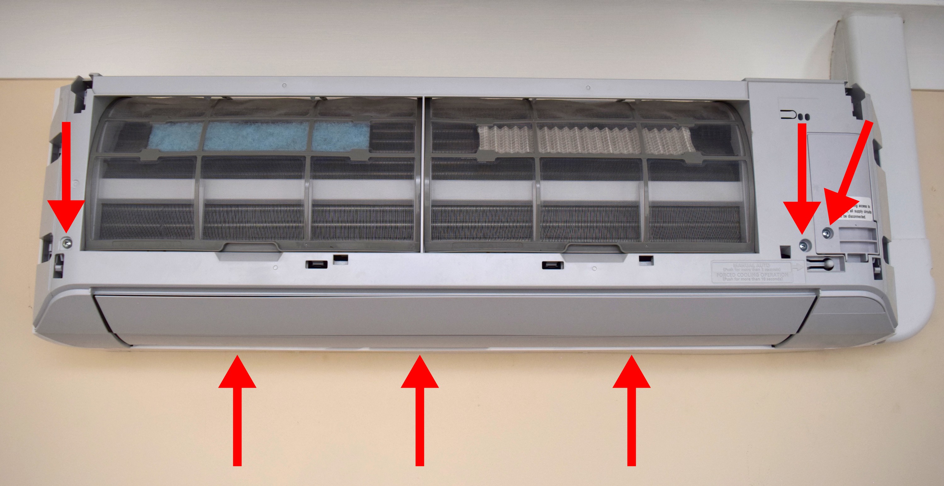
To take off the outer shell, I had to remove 7 (Philips #2) screws.
- One in the terminals cover on the right
- One in the bottom right underneath that cover
- One to the bottom left just outside the terminals cover
- One on the bottom left on the front of the shell
- Three on the underside of the device, after removing the screw caps
After those screws were removed, it was a bit tricky to pull the case off the innards. I had to tweak the bottom and the top a bit to avoid pieces getting caught. Removing the air filters made it a bit more comfortable even though it’s not strictly necessary. After jiggling and tweaking plenty it came loose with noises that weren’t too concerning.
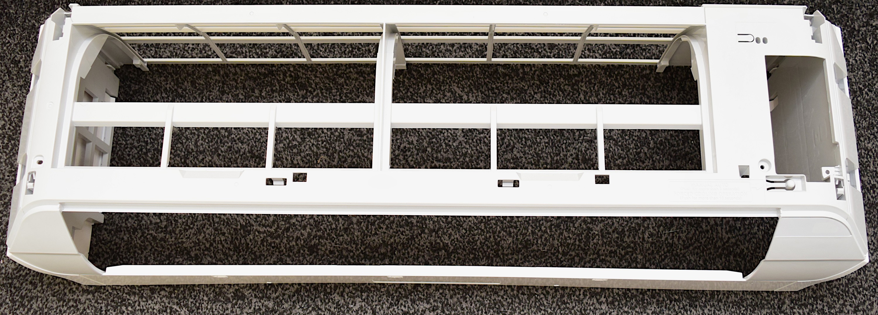
Here’s a photo of just that outer shell.
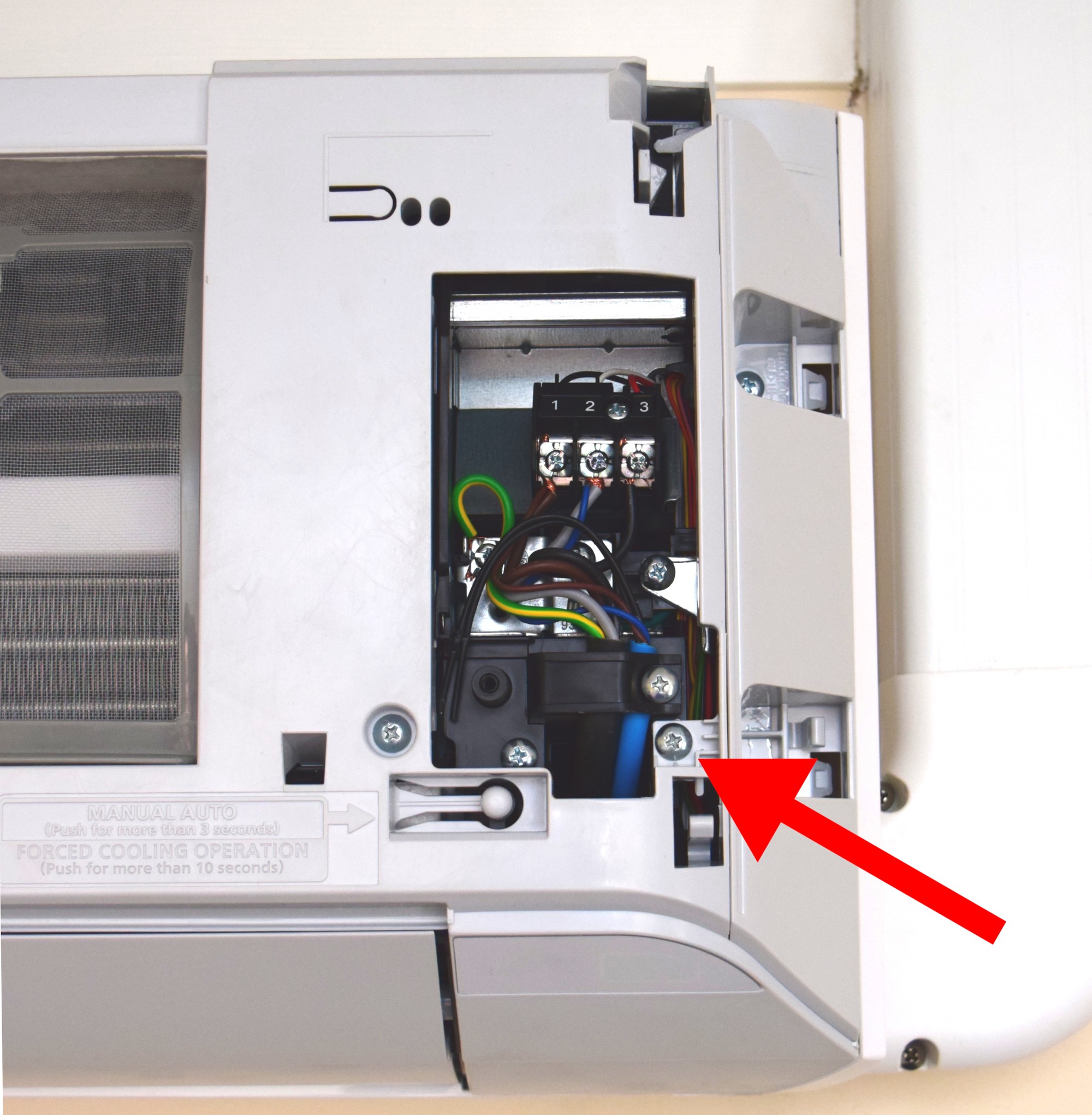
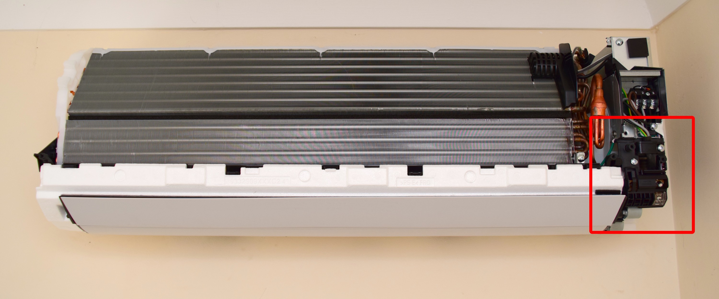
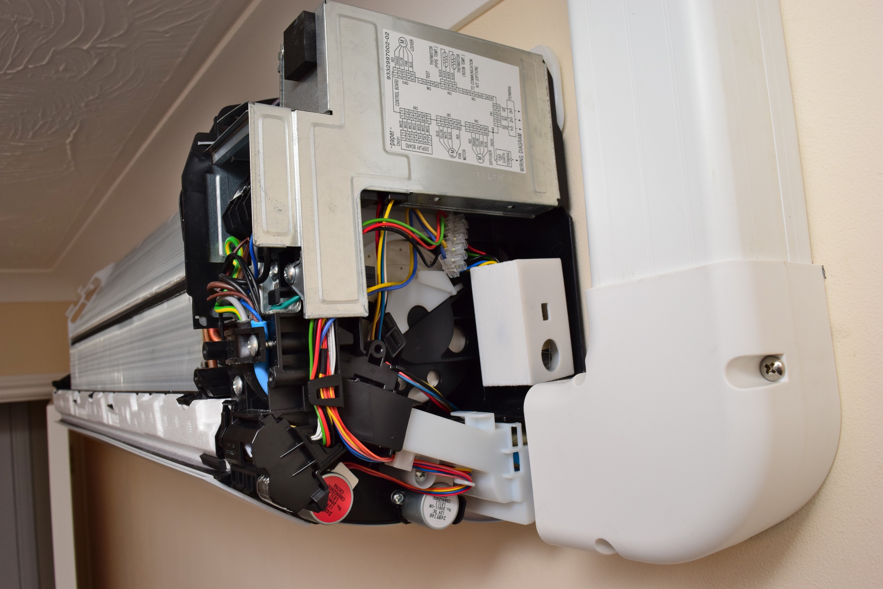
This left the A/C Unit bare. The remote control receiver is in the bottom right black bit so that’s what I focused on next.
Taking a closer look, the sensor sits in a detachable assembly that is latched onto the main body of the unit.
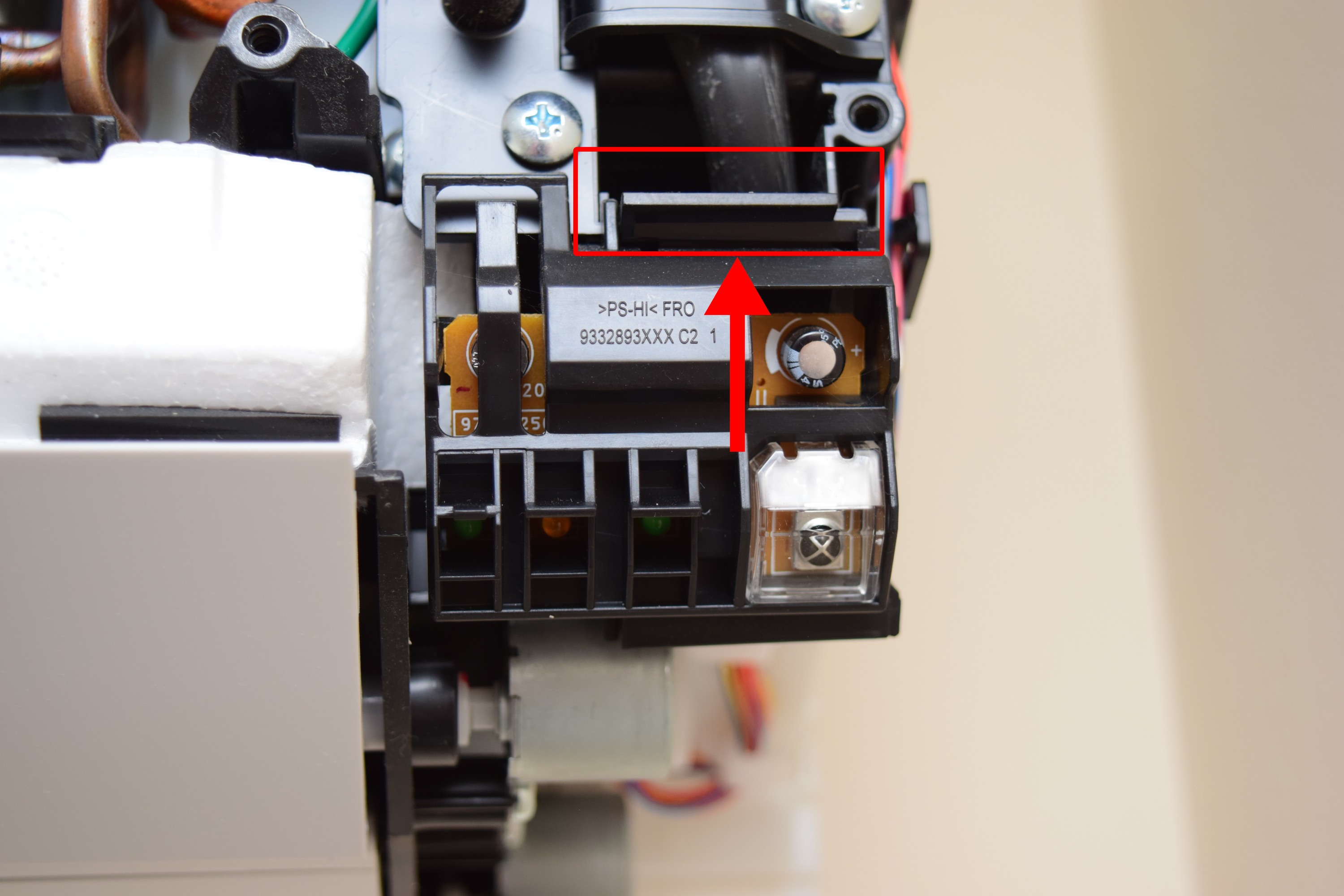
I pressed the latch up, and the module popped right out.
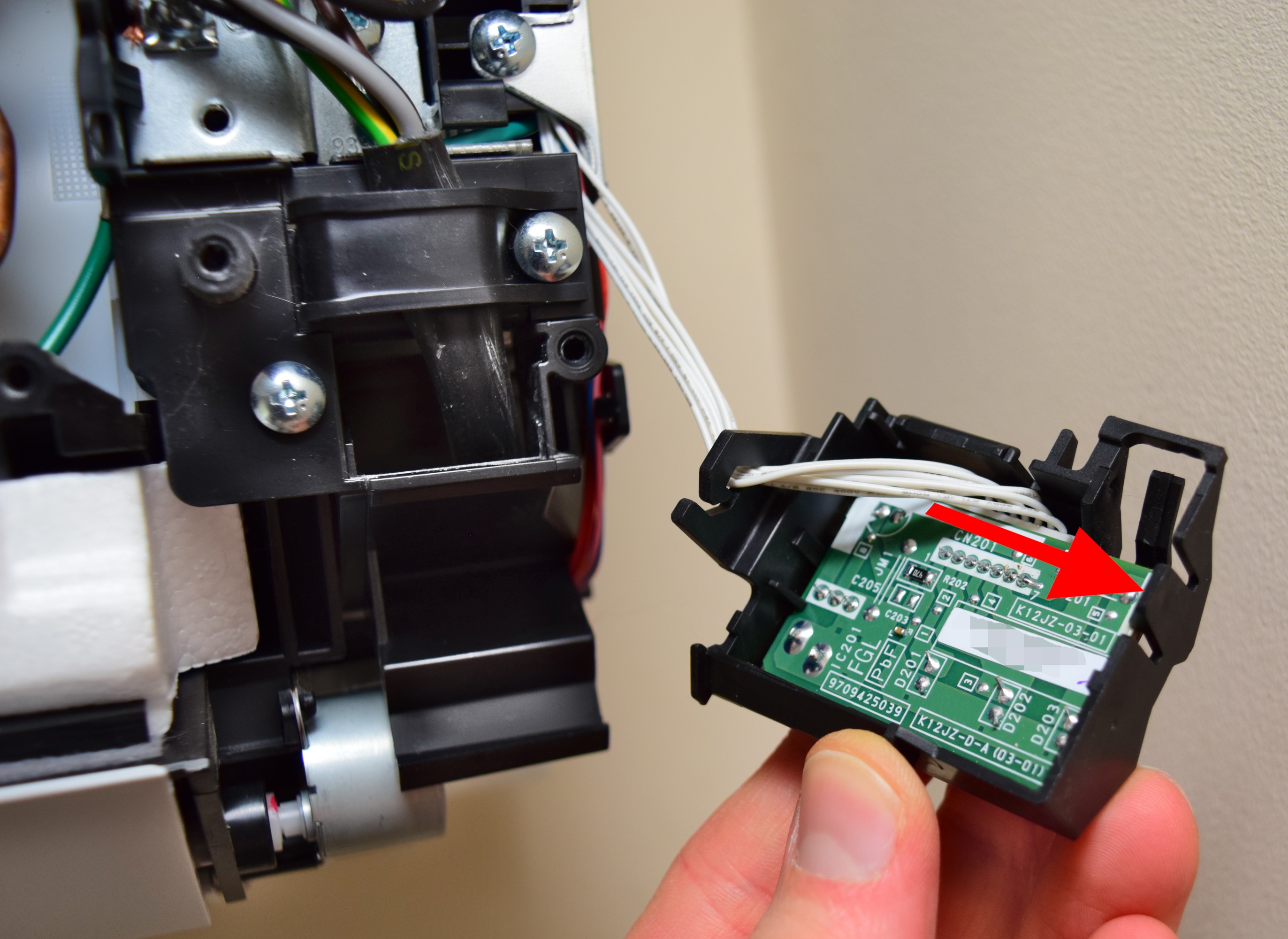
On the back of this I found another latch holding the PCB in. Pushing this latch out allowed me to lever out the board from the top right. I carefully disconnected the cable, and just like that, had a PCB to investigate.

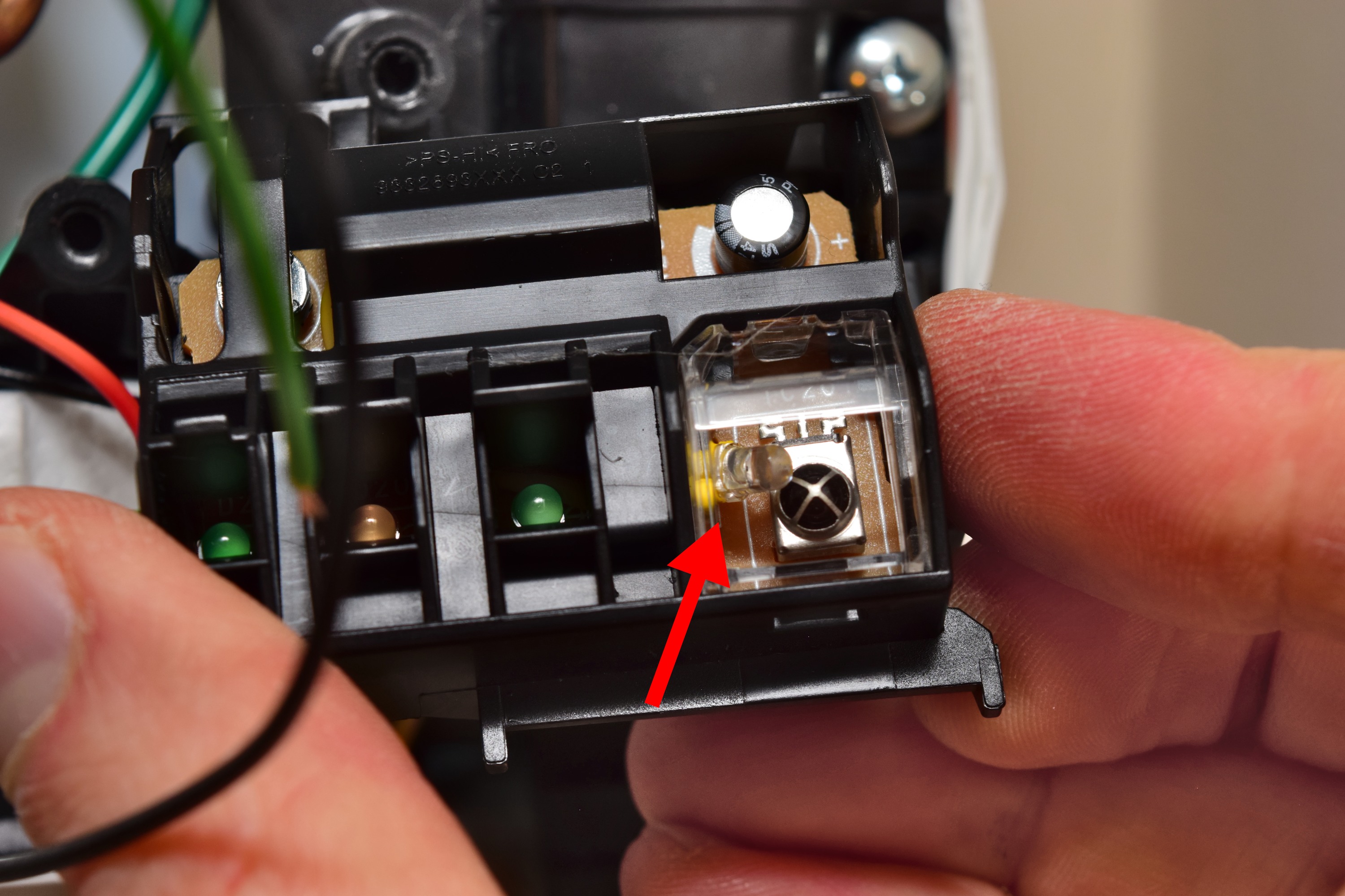
The button in the top left is a manual test button. This appears to be a simple normally-open push button. The connector is a JST S7B-PH-K-S(LF)(SN): 7 pins, right angled 2mm pin pitch. The LEDs appear to be pretty standard 3mm indication LEDs, green, yellow, green. I’m afraid I didn’t see a clear part number on the infrared receiver, but it appeared functionally but not pin-compatible with the VS1813B I used on my board.
Flipping the board over:
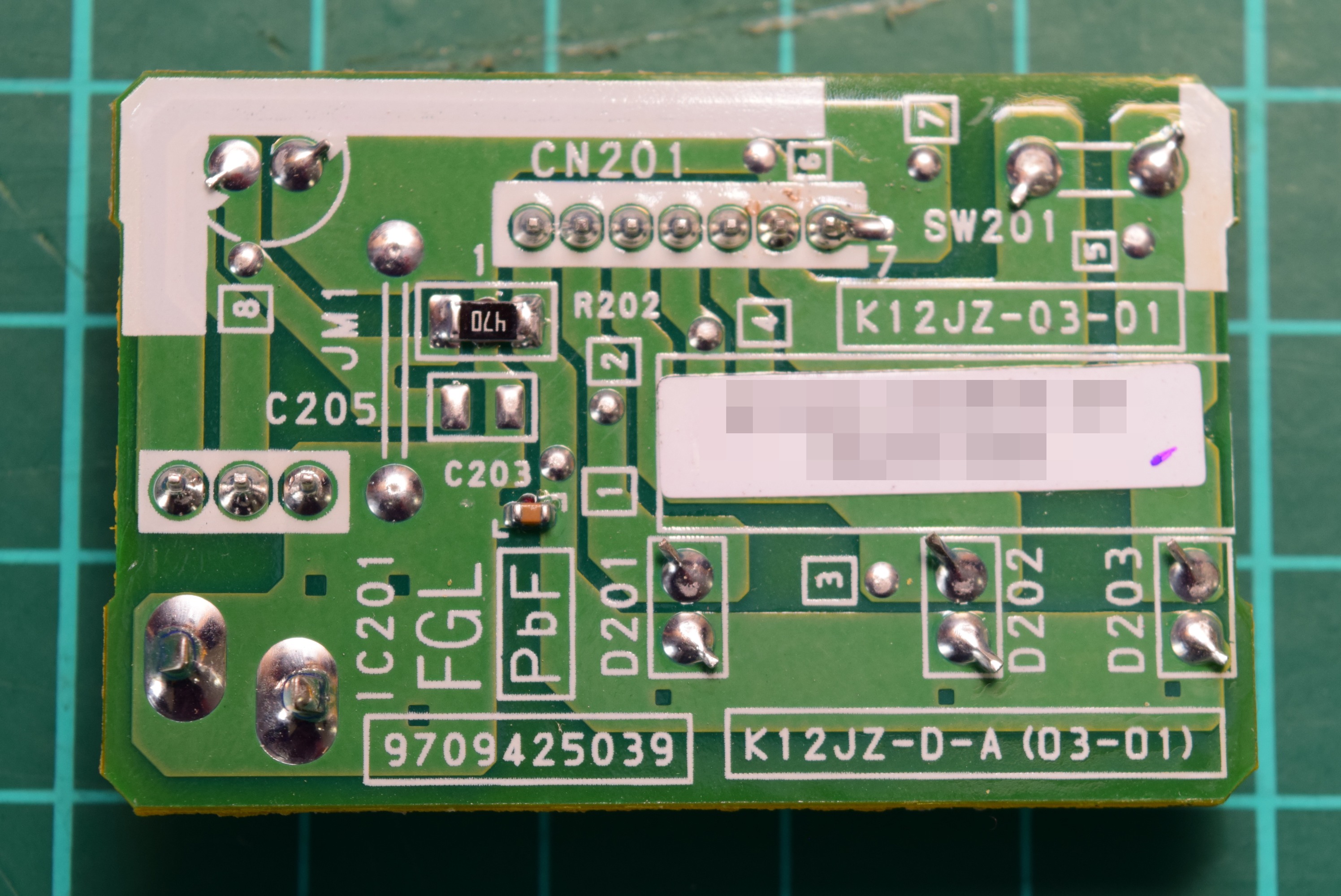
A 470 ohm resistor forms a passive low pass filter with the electrolytic capacitor at the front. This is connected to the board’s positive power line, and forms the power supply to the IR sensor. There is also a small capacitor as a bit of energy storage on the board level.
At this point it’s worth listing the goals:
- Steal some power from the A/C unit to power our ESP32 thing, so the USB cable isn’t needed anymore
- Inject messages to control the A/C unit
- Spy on what the IR receiver sees, so normal remote control usage cooperates with the Home Assistant integration
I considered “bypassing” the IR receiver and sending it data directly, but opted for simply squeezing an infrared LED next to the receiver. I already had something that works, without having to learn about modulation and demodulation of the IR signal. Since the IR receiver demodulates the signal before sending it to the A/C unit’s microcontroller, my module would need to send demodulated data, which entails more complicated firmware work than, well, not doing that.
With that in mind, I only cared about 3 nets on this board: the power lines (positive and ground), and the output of the IR receiver. I probed around with a multimeter and annotated the photo of the board.
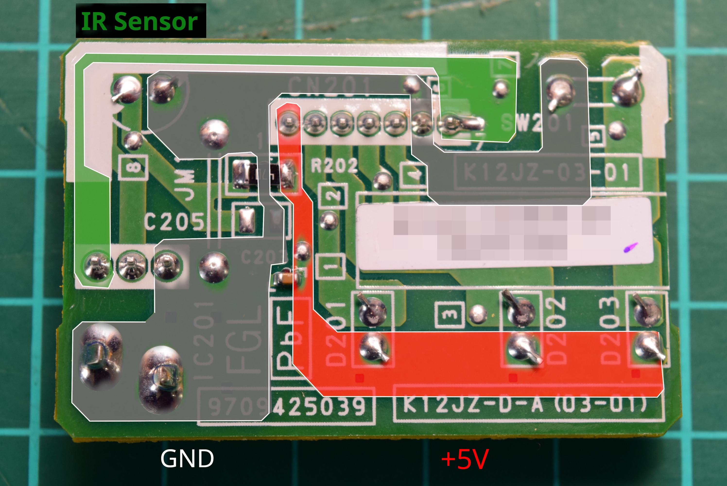
At this point I didn’t know what voltage this board ran on, but I knew what connector pins to probe. I reconnected the board to the A/C, briefly powered the system up, and measured: 5V, as expected.
Hacking the A/C’s IR receiver board
Note: I’m pretty sure this is entering warranty-voiding territory. Considering this PCB is very simple and easy to replace, I figured the risk was low enough to go ahead.
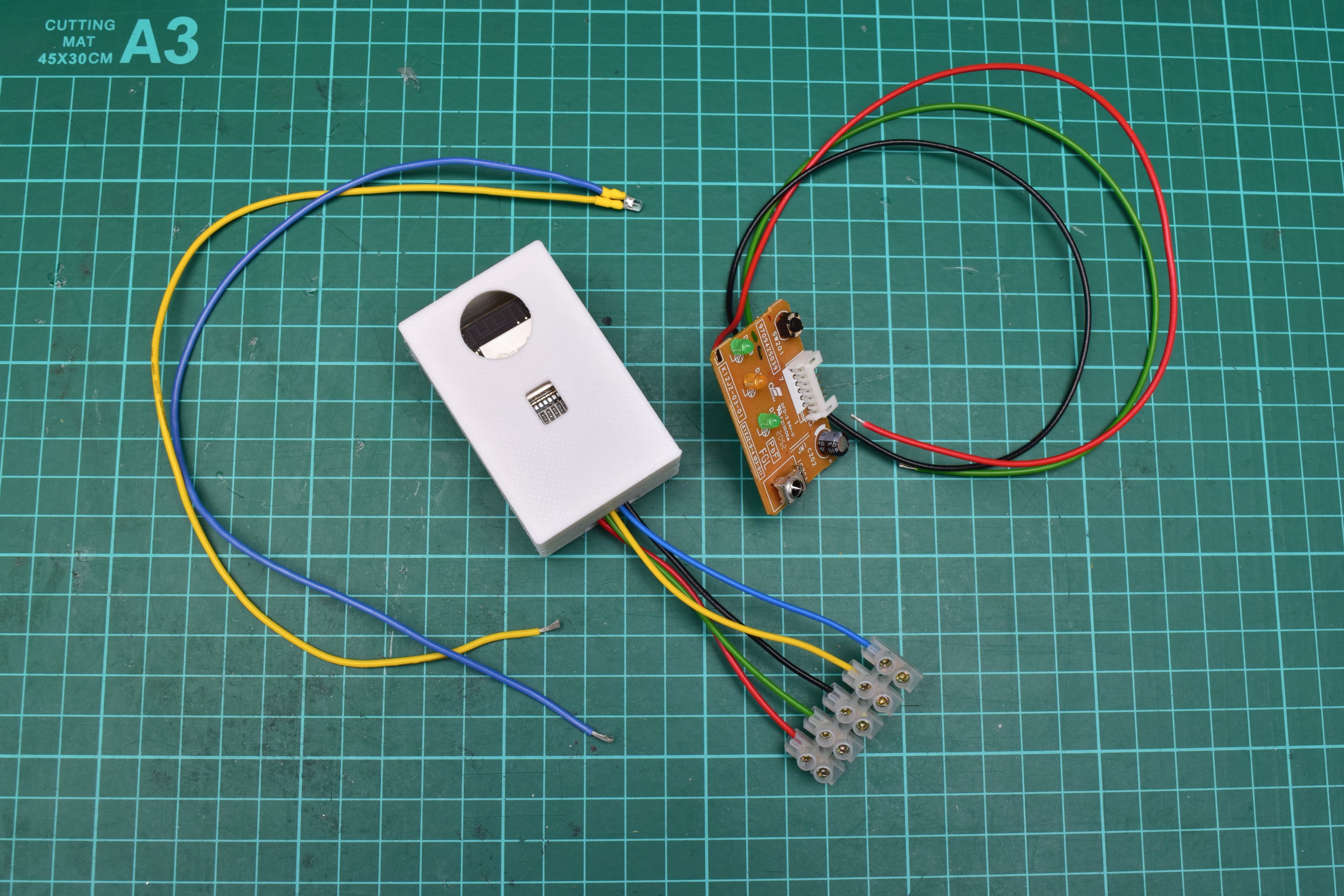
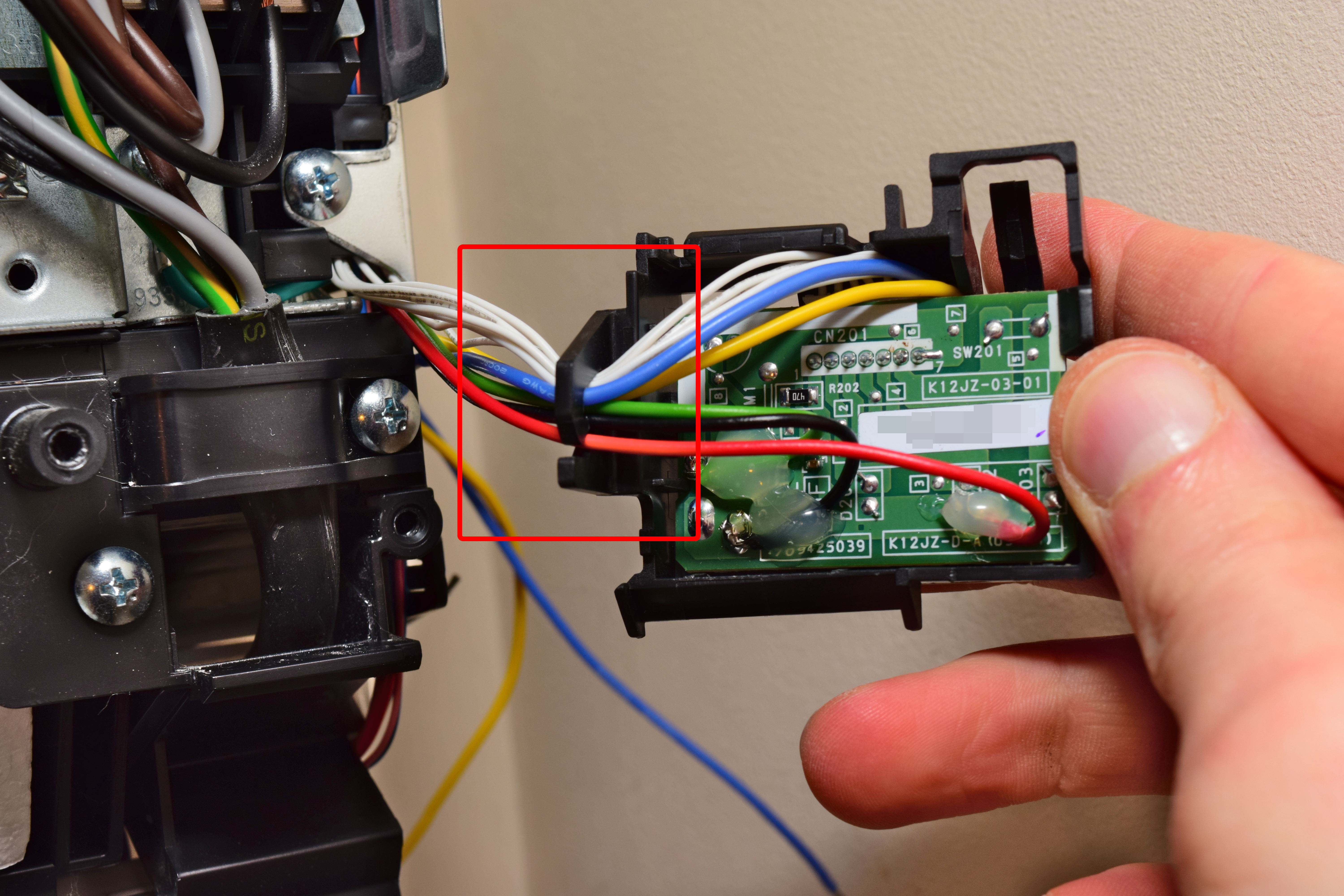
I cut and stripped some wires: red, black, green, yellow, and blue, all cut to about 30-35 cm. I soldered the wires onto the annotated areas where it seemed most practical, then put a glob of hot glue on each of them so they wouldn’t easily break off and potentially damage the board.
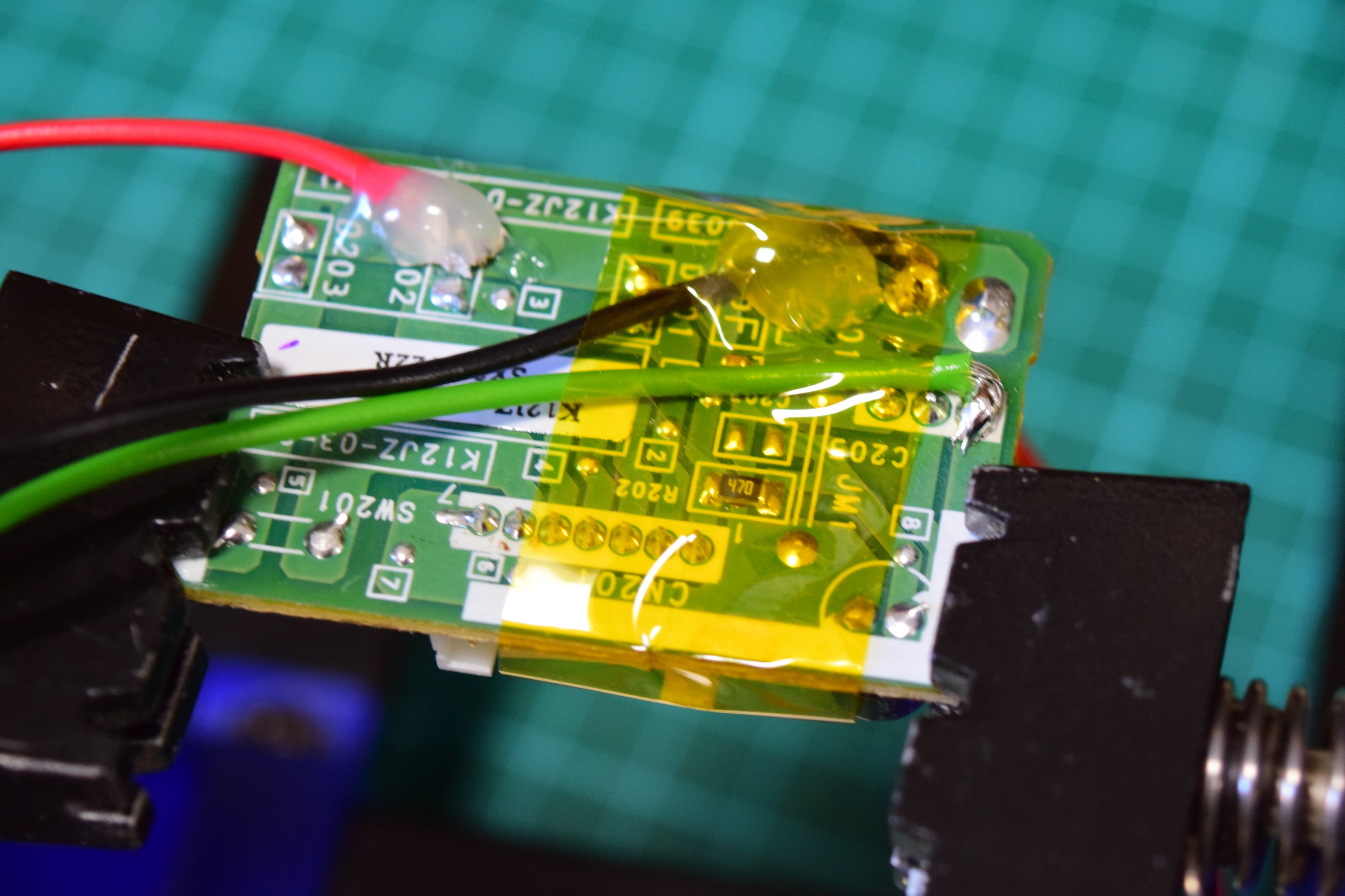
Here I’ve just soldered the IR sensor wire (green). I held down the wires with heat-resistant polyimide tape for soldering.
I trimmed the leads of a 3mm infrared LED, and soldered the yellow (anode) and blue (cathode) wires onto it. I then insulated the connections with heat-shrink. I chose more flexible wire for this, because the LED had to be squeezed into a tight corner.

Adapting esphome-ir-box
With the A/C’s electronics done, I turned to the esphome-ir-box board. I removed both the IR LED and sensor, to replace them with wiring to external ones.

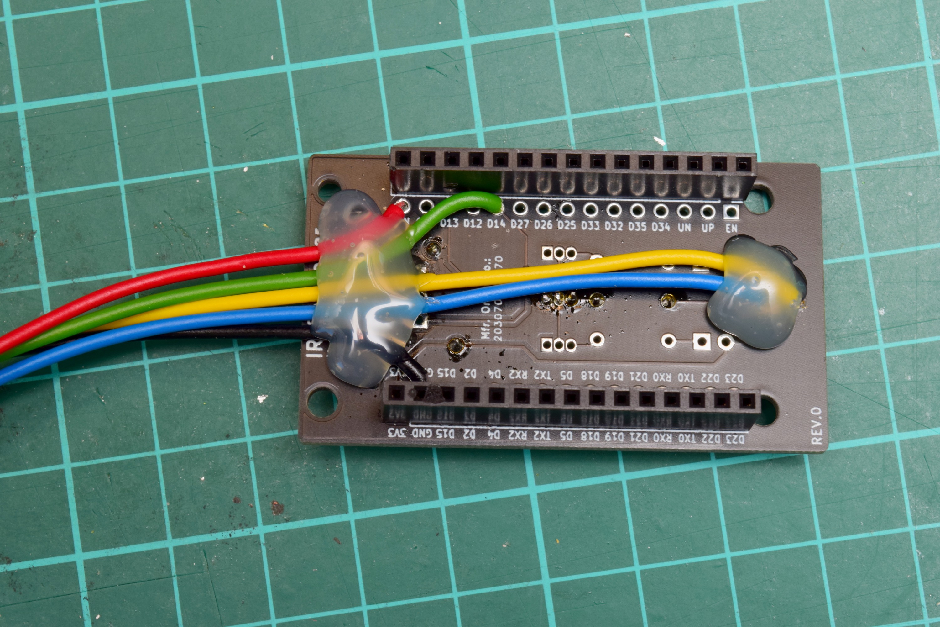
I then cut and stripped another 5 wires in the same colours as before. This time I trimmed them to about 20 cm. Yellow and blue went into the pads of the LED footprint. Red to Vin (normally connected to USB +5V), black to ground. Green, for the infrared receiver, goes to D14, like the on-board IR receiver did. I was pretty glad I included these extra connection points in the design.
After soldering those wires, I threw a bunch of hot glue on there to solidify it all, resulting in this:
I plugged the ESP32 dev board back into this PCB and stuck it back in its box, re-purposing the USB cable hole for the new wires. I trimmed the the wires to stick out around 8 centimetres, and attached a block of screw terminals.
Installing the modifications
With all these bits done, it was ready for installation.
Warning: If you’re following along, ensure you flash the ESPHome firmware onto the ESP32 board before installing it into the A/C unit. The first time flashing requires a USB connection. Scroll to the bottom of this post for more details on the firmware side.
The tricky part here was to get the IR LED pushed into the chamber with the little window, while clicking the PCB back into the plastic housing. I managed it without obscuring the sensor too much. The orientation of the infrared LED doesn’t seem to matter; as long as it’s in the chamber, the proximity and perhaps reflection in the window ensures the receiver picks up on it.
On the back of the module, I routed the new wires along the existing ones, through the hook on the left of the assembly.
Finally, I routed the wires into the open space in the back of right of the A/C. From there, I connected the wires to the screw terminal block and left the box in the open space.
I then turned on the A/C circuit again to test the integration (having previously flashed the firmware):
- Does turning it on/off from Home Assistant work?
- Does turning it on/off from the normal remote work?
- Is Home Assistant aware of changes made with the normal remote?
All worked fine, so I was happy to put the thing back together after turning off the power again.
Once reassembled, there was no visual difference to the unit; a much better end result than having some ugly boxes hanging around on the wall.
Home Assistant / ESPHome setup
That’s was the hardware out of the way. I thought I’d give some details on how it’s configured in Home Assistant as well.
I have both Home Assistant and ESPHome running via the Docker installation method. It’s running on an old laptop, and this method works great for me.
In ESPHome’s web interface, I used “Create new device”, named it, and picked “ESP32” as the device type. I skipped installing immediately, and went to edit the configuration file.
In the WiFi section I did set a manual IP address, as I like to maintain a file with everything that’s on our network; static IP addresses make that more maintainable for me.
wifi:
  ssid: !secret wifi_ssid
  password: !secret wifi_password

  manual_ip:
    static_ip: 192.168.1.43
    gateway: 192.168.1.1
    subnet: 255.255.255.0
Then, the IR and air conditioner configuration:
sensor:
  - platform: homeassistant
    id: "dining_room_temp"
    name: "Dining Room Temperature"
    entity_id: sensor.dining_room_t_temperature

remote_transmitter:
  pin: GPIO13
  carrier_duty_percent: 50%

remote_receiver:
  id: rcvr
  pin:
    number: GPIO14
    inverted: True
    mode:
      pullup: True
      input: True
  tolerance: 55%

climate:
  - platform: fujitsu_general
    name: "Dining room AC"
    receiver_id: rcvr
    sensor: dining_room_temp
    visual:
      min_temperature: 16
      max_temperature: 30
      temperature_step: 1
Some notes on this configuration:
The sensor section makes this device aware of a temperature sensor known to Home Assistant. This is an external sensor, in my case it’s a SONOFF SNZB-02. This is needed, because Home Assistant’s “climate” integration needs to know a temperature for the area where you’re controlling the climate. This sensor, here identified as dining_room_temp is later referred to in the climate section of the configuration.
The remote_transmitter section tells ESPHome what pin the IR LED is wired to, and configures some options about the carrier waveform sent to it. This is about the extent of involvement with sending infrared.
remote_receiver, as you might expect, sets up the IR receiver. It is connected to pin 14, and some more options are configured. The mode options may be redundant here, I’m not too sure. The inverted: True bit was suggested by ESPHome’s log output when initially experimenting with this. It detected the initial output of the IR receiver and suggested this option to read it correctly.
Finally, climate configures the climate control integration to use the IR hardware. Specifying platform: fujitsu_general was all it took to make it talk to these A/C units; someone had already done the hard work of making it happen. A name for climate control is also specified. This is how it will be known in Home Assistant. The IR receiver rcvr is mentioned as well, allowing it to pick up on the regular remote. I assume it automatically finds the remote_transmitter section as there was no need to specify it here. The temperature sensor mentioned earlier is also listed here, to show the current temperature in the climate UI in Home Assistant. The visual section configures the range of adjustment. I set these based on the limits available on the regular remote.
Installing the firmware
For the first installation, I clicked the three dots on the item in the ESPHome dashboard > Install. In the menu, I selected “Plug into the computer running ESPHome Dashboard”.
As you might expect, I plugged the ESP32 board into that computer. If you’re following along, I hope you heeded the warning earlier. :-)
A side note for ESPHome run through Docker: When I plugged the device in while ESPHome was already running, it did not show up as a programming target. I had to restart the docker container to make it see the new USB device.
I selected the relevant device, and let ESPHome do its thing. It put together some C++ source code elements from the YAML configuration file, compiled it, and flashed it onto the device. After that I could go put it wherever it could reach the configured WiFi network. Any future firmware updates could be installed with the extremely convenient “Wirelessly” option.
Home Assistant setup
Over in Home Assistant, I immediately got a “new device found” notification, on which I clicked “set up” or something similar. I provided the API key found in the ESPHome dashboard > Edit on the device to let Home Assistant talk to it, and it was ready to go.
Adding to a dashboard
At first I added climate control to a dashboard by editing the dashboard, clicking “Add card” > “by entity”, and then searching what I named the climate component in the ESPHome configuration file. I ticked that item, “continue”, and “Add to dashboard”, and there I had a convenient (ish) controller for the A/C unit.
The Home Assistant-provided climate control card is quite large and a bit annoying to use. I’m using some of the custom “mushroom cards”, that is, third party-created dashboard cards for Home Assistant, which include a much neater compact air conditioning control UI. On our main dashboard, we now have this:
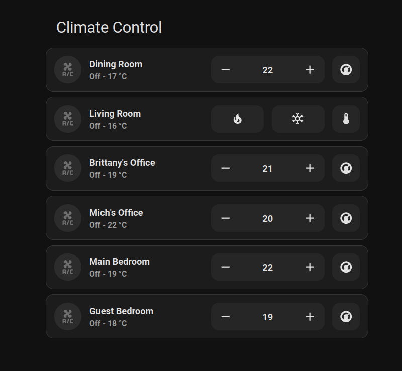
This gives all the control we need in very little space.
That’s it!
That’s about all I have. All in all, this was a fun project, and I’m happy with the results.
Some further developments that I think would be cool:
- A compatible PCB to replace the stock one from the A/C unit. This PCB would have a connector for the ESP32 setup, so no modification to original electronics is required.
- Expand integration to monitor the status LEDs of the A/C. That way it would be possible to monitor whether it was set to economy mode, or, if the left LED is blinking, detect issues.
- On the firmware side, integration of some specific features of this A/C unit, such as economy mode, powerful mode. These are not currently supported by the “climate” integration in home assistant or ESPHome, so it would be neat to add them manually.
For now though, I’m satisfied. I think I’d rather focus on getting some automations set up to automatically heat or cool based on some external context, a schedule, and/or our presence in the house.
Here’s hoping the A/C installers don’t scold me too much next time they come by for a maintenance round. :-)