FPGA MIDI Synth update: MIDI improvements, Polyphony, PWM etc
Since school has ended, I’ve played with our yearproject some more to make it more awesome and usable. Here’s an update of what fun stuff I’ve been doing to it. I’ve purchased my own Digilent Nexys2 board, so I can keep working on this and future FPGA projects now I’ve returned my ex-classmate’s board.
MIDI improvements
The most important problem we had was that MIDI interpretation was terrible. Sure, it worked, but once you’d start playing faster than 115BPM, notes would randomly be missed. At school, we had actually spent weeks trying to figure out where in the code of the UART or MIDI interpretation we did something wrong.
During my later fiddling, I found out that the reason for this was that there were a couple of elements in the FPGA design that weren’t triggered on the rising edge on the clock, but rather on the rising edge of some combinatorial signal. This caused all kinda of synchronisation errors, and thus the quite timing-sensitive MIDI interpretation. The issue was resolved easily by adding a clock input to the elements that were without, and altering the code to something like this:
if(rising_edge(clk) and combinatorial_signal = '1') then
-- statements to be executed
end if;
Testing that change made it all work pretty much perfectly. From what I could hear, it played 16th arpeggios at 999BPM without any problem.
After that, I tweaked the design a little more in order to make it play different waveforms when different MIDI channels were being used. With that properly implemented, I could fake polyphony by rapidly switching channels. Here’s a video that demonstrates it. The LEDs lighting up indicate which channel (and thus waveform) is currently being used.
Polyphony and PWM
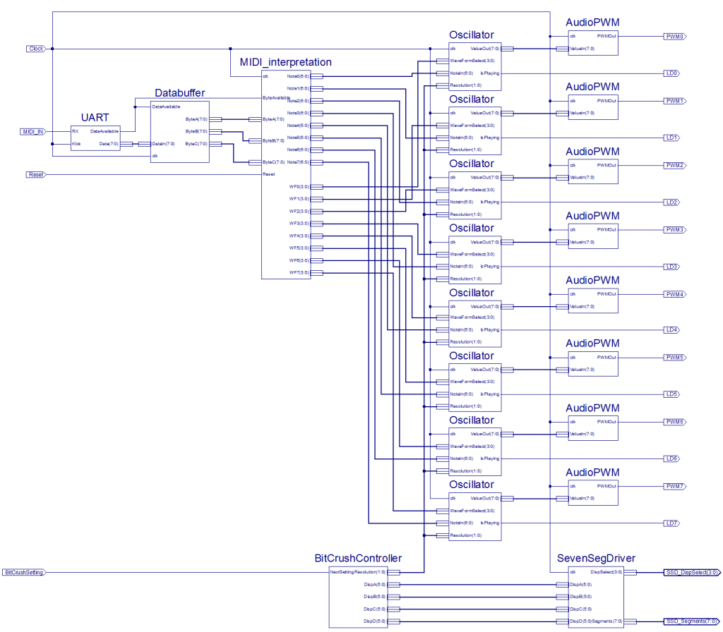
Still excited about the fixed MIDI, I realized I could probably make the synth a lot better, since I now had the most problematic part worked out. A synthesizer isn’t worth much if it can’t handle polyphony, so I decided to have a shot at that. I rewrote the MIDI interpretation VHDL module to keep 8 voices in memory. Then, I changed up the sound generation part so I would simply have an “Oscillator” block to go from an “OutSpeed” input to the Digital Audio output. This made it quite a bit more modular. Since my new MIDI interpretation block had 8 OutSpeed outputs, I made 8 Oscillator blocks, and routed them all to a new block I named “Mixer”.
I spent a couple of hours trying to get the digital signals mixed together, but I had a hard time doing so. I have to admit I failed utterly. The output sounded either horribly clipped, completely out of tune, or just noisy. Eventually I gave up this approach and decided to do the actual mixing externally, and thus in an analogue fashion. I had heard about Digital to Analog conversion using Pulse Width Modulation (and it was quite clear to me how to do this), so I decided to give that a go, with success.
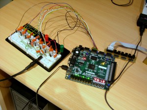
In Xilinx ISE, I made another new module, called “Audio_PWM”, which would convert a typical 8 bit number to a high-frequency PWM signal. This way I only needed a single output pin to get the audio out, rather than the 8 pins going to the DAC PCB. I’m still using 8 pins, but this time they are to output 8 different voices. I breadboarded (if that’s even a word (if it isn’t, it is now (also, nesting parentheses is fun (ANYWAY)))) 8 simple low pass filters and a typical summing amplifier circuit, which is pictured below. This circuit took over the job of the digital mixer I failed to make, so I tossed the latter away.
The summing amplifier feeds the resulted voltage to my active speaker, which also takes the need for the little amplifier + speaker away, which in turn reduces the number of elements of the synth quite a bit.
The connection cable pictured here is one I crafted from some pin header connector (which fits into the FPGA board’s connectors nicely), and a bunch of wires I had lying around. On the other end I soldered pins from the same type of connector, but individually, so it makes for easy but solid connection with a breadboard. I used some heat-shrink to make it all a little more sturdy.
Anyway, for this breadboarded circuit, I’ve also designed a PCB, which I’ve yet to have made. I’ll make a new post with pictures once that’s done. (Or earlier if I make any new awesome progress).
Now for a video of the synth’s capabilities at this point. I had it play Hot Butter’s classic “Popcorn” for a demonstration. Here and there it still missed a “note released”, which I haven’t been able to fix yet; I think it occurs when a whole lot of MIDI actions are sent at once, which is plausible in a song like it. I can tell you that it plays flawlessly on my MIDI keyboard though.
7 Segment display usage
I decided that if I wanted to make the synth more feature-rich, I’d have it display some information as well. Since Digilent’s Nexys2 has four 7-Segment displays on board, this seemed like the best option to start out with. I started a new project and wrote up a single VHDL module, “SevenSegDriver”. This module has 5 inputs: clock, DispA, DispB, DispC and DispD. All the Disp inputs take a binary number representing a character, ranging from ‘ ‘ (empty screen) to ‘z’. Seeing as there are only 7 segments to play with , not all characters can be displayed properly, but I did my best with the help of good old Wikipedia.
The outputs for this driver are “DispSelect” and “Segments”. DispSelect simply only makes one of the displays active at a time, and cycles them so quickly you can’t see it with the naked eye. Segments outputs the current display’s number to turn on the right segments. This makes the driver basically a decoder and multiplexer/demultiplexer in one.
Once this was tested properly, I ported it to the polysynth project. The information I’m displaying is about the currently set waveform resolution, but is likely to be expanded to other options in the future.
Waveform resolution setting
As I mentioned, I made a waveform resolution setting. I tweaked the oscillators module (and in there the waveform sample selector) to have a resolution input. This allows me to choose between 8 bit, 4 bit, 2 bit and 1 bit. This basically describes in how many possible values a waveform is divided. (Not on the time axis, but on the volume axis). If you have a lower resolution, it all sounds more square-y than it does with a high resolution, which isn’t all that surprising, since the waveform looks blockier when displayed.
What I intended with this resolution thing was to create a sort of bit-crushing effect. However, since I’m applying the resolution change on each voice oscillator individually, it doesn’t sound very amazing on the summed waveform. It probably sounds a lot more interesting if I could do it on the sum, but seeing how mixing it digitally didn’t work out, I’ll have to be happy with what it is.
I made a little controller block which remember the current resolution, and allows to cycle through the 4 possible settings with the press of a button. The controller also sends the information out to the seven segment driver mentioned earlier. This all explains why it says “4 bit” on the screen in the photo somewhere up there.
Future plans
As I mentioned, I’m going to have a nice PCB made of the PWM mixer circuit so it’s all a bit more sturdy and nice looking. On the software part, I’m looking to take into account the third byte of the MIDI messages, namely the velocity, to regulate a note’s volume. This will lead to the MIDI interpretation block having 24 output buses, but I guess that’s not much of a problem. In the possibly more distant future, I want to build a sampler component as well. For that, I’ll first have to build an analogue to digital converter; that is, if I actually want to record them with the synth itself. The other option would be to hard-code them in the design as the waveforms currently are. I might want to get a PROM to attach to it, which can load the samples in on start-up, but those are just some faint ideas.
Current FPGA design schematic
It got quite big. (Click to enlarge)

