DIY: Garage to Workshop Conversion
In June 2021, my partner Brittany and I realised a dream: we bought a house. When viewing the place, the owners showed surprise about us wanting to have a look at the standalone double garage. It was packed full of unwanted stuff, leaving barely any room to walk. As “makers”, we had some different ideas for the space. Soon after we got the keys, we got to work.
Let’s get the before/after out of the way before going through the whole thing.
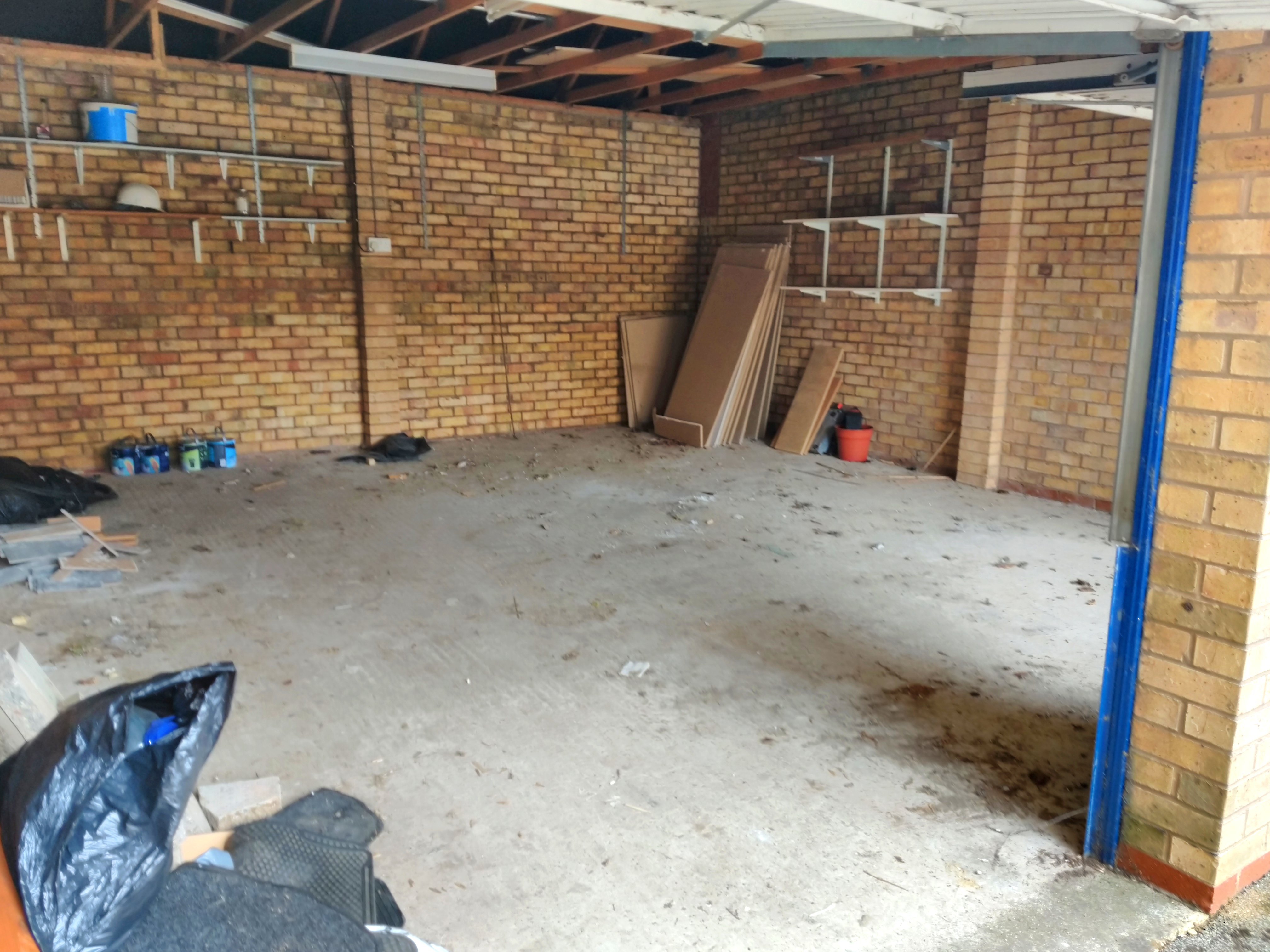
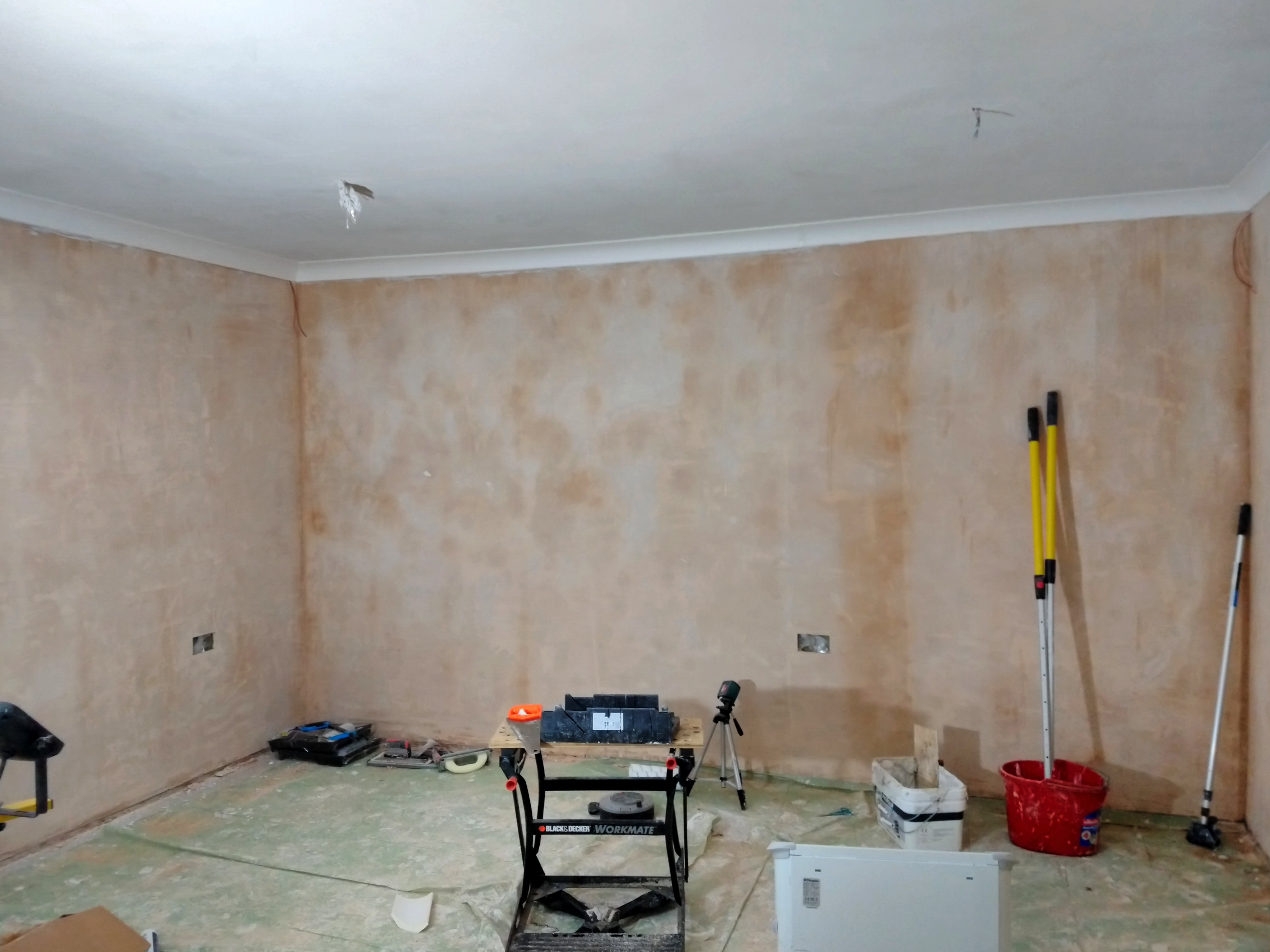
Before
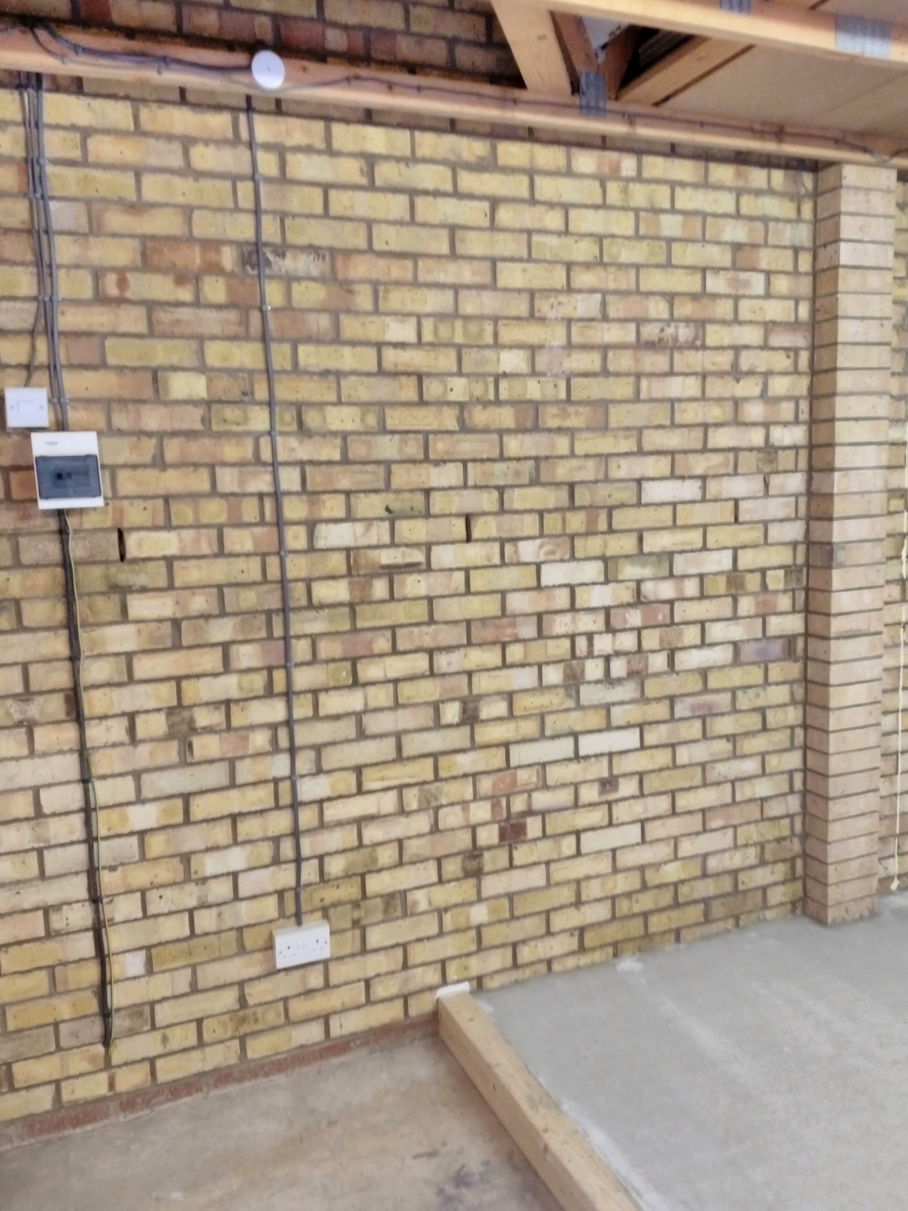
How we found the garage on the day we received the keys, June 11th. The previous owners cleared out most of their stuff, but left us a few things we might find useful.
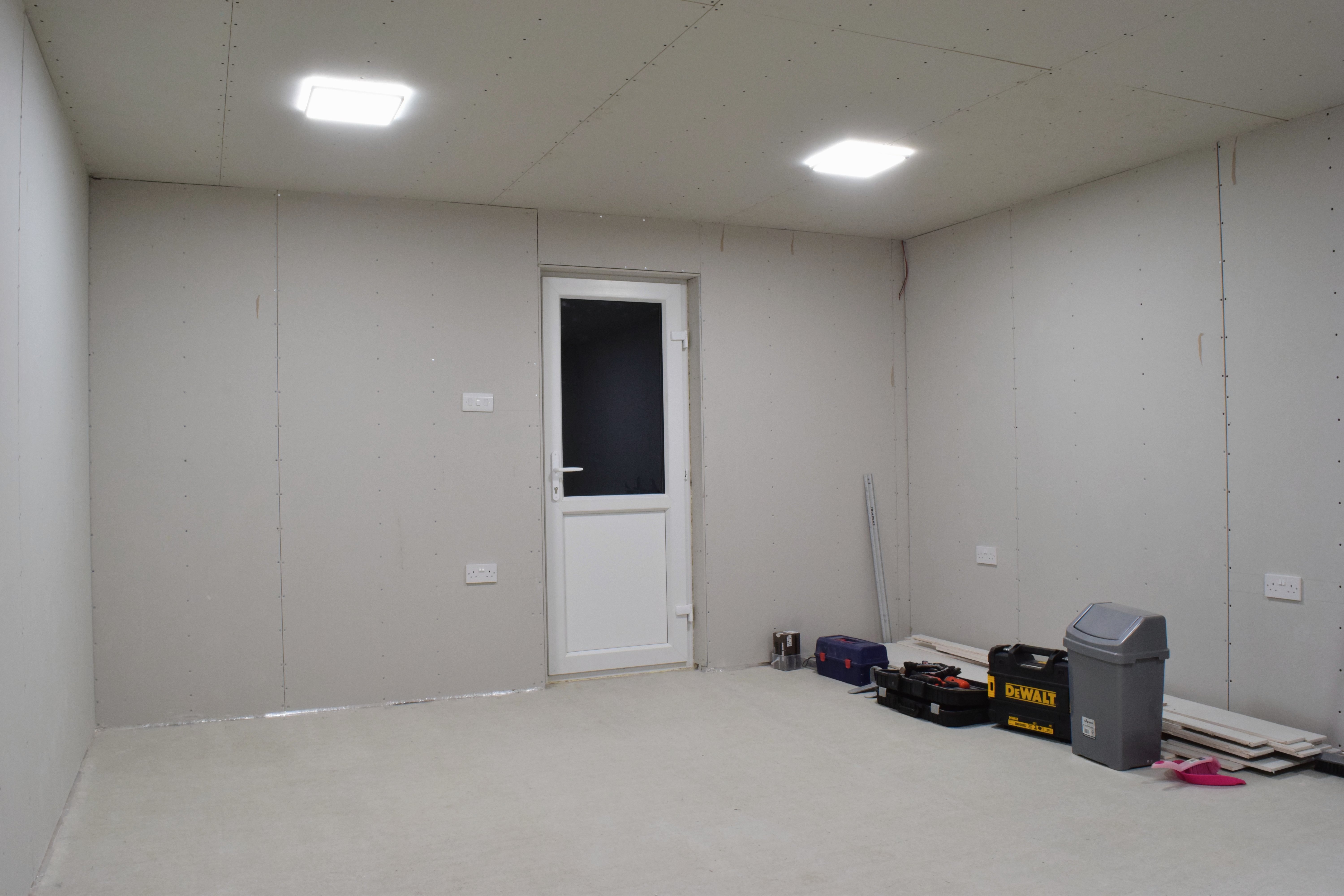
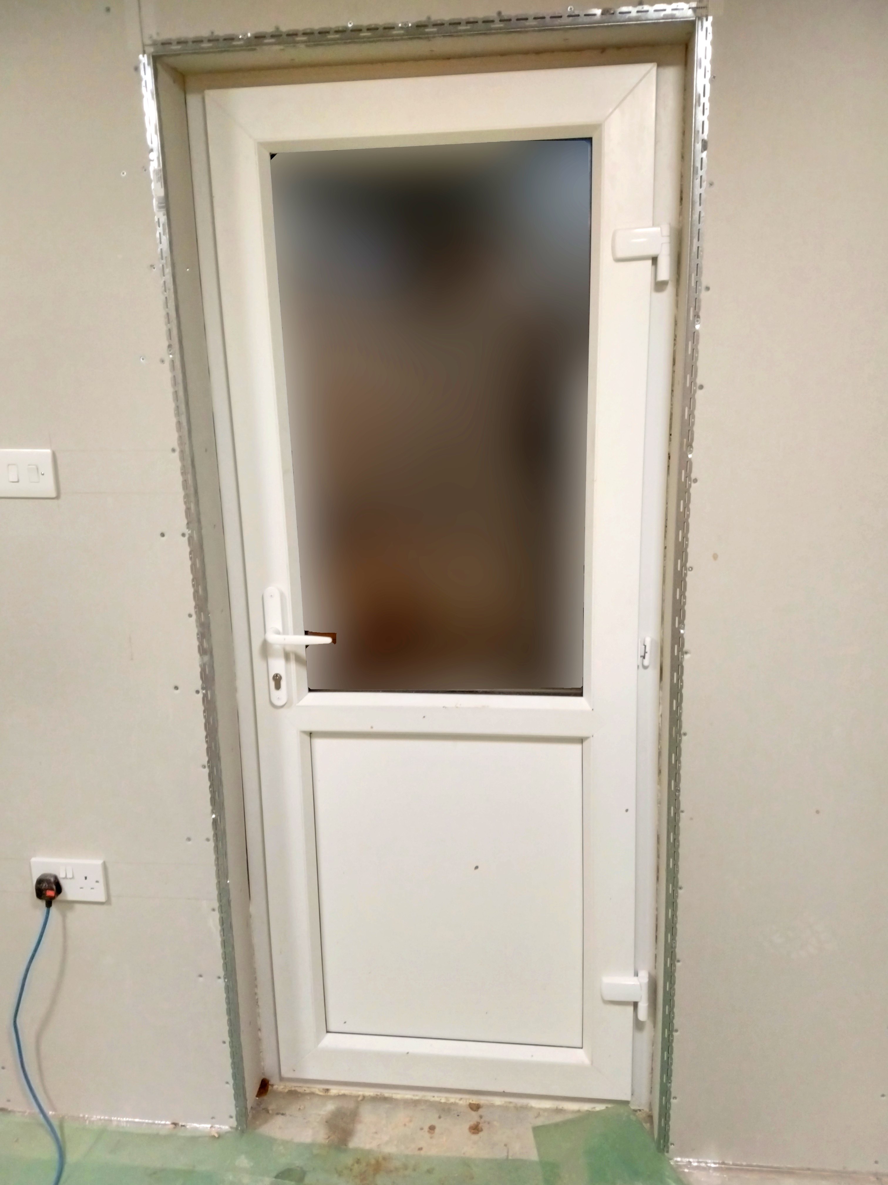
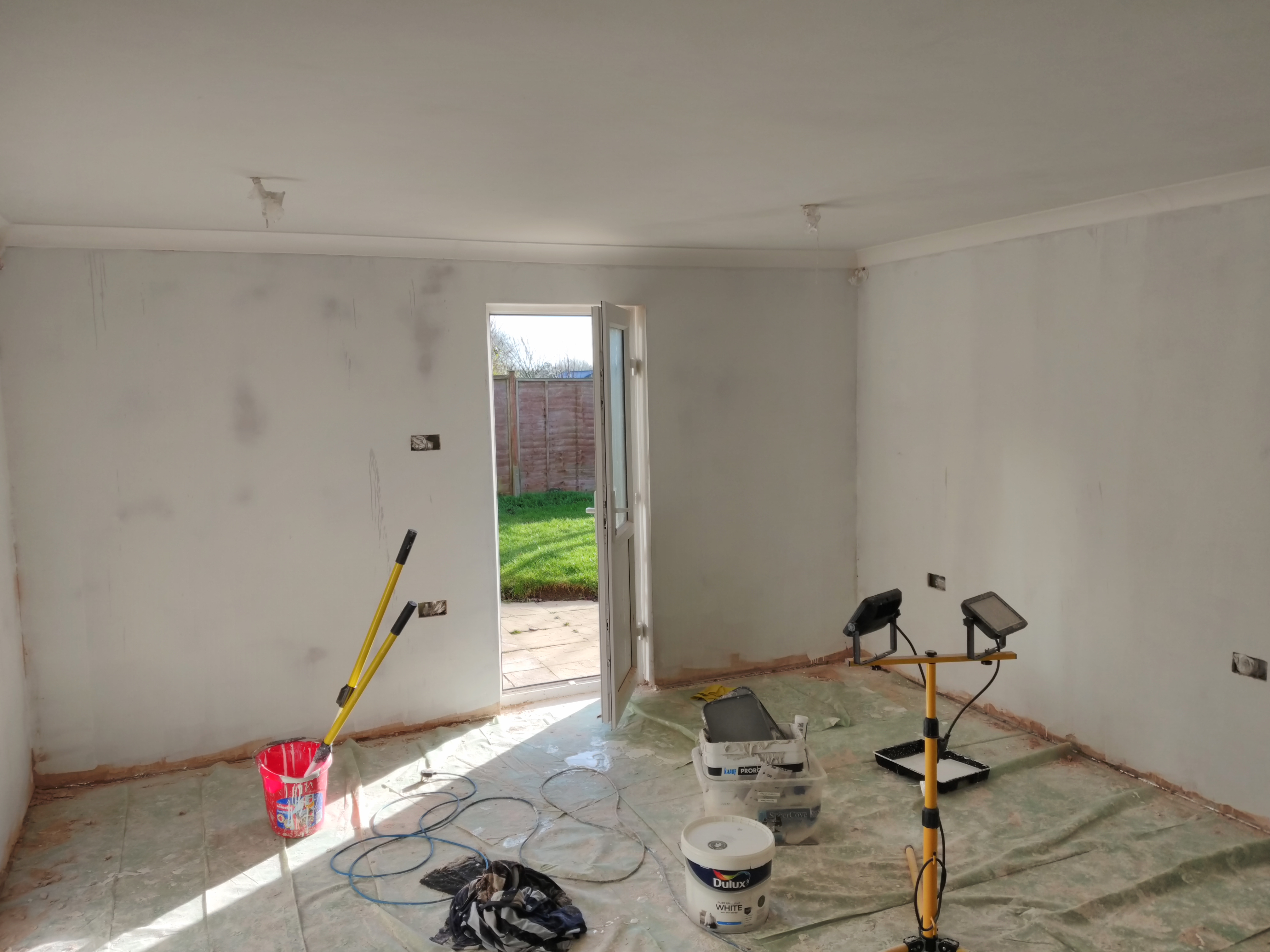
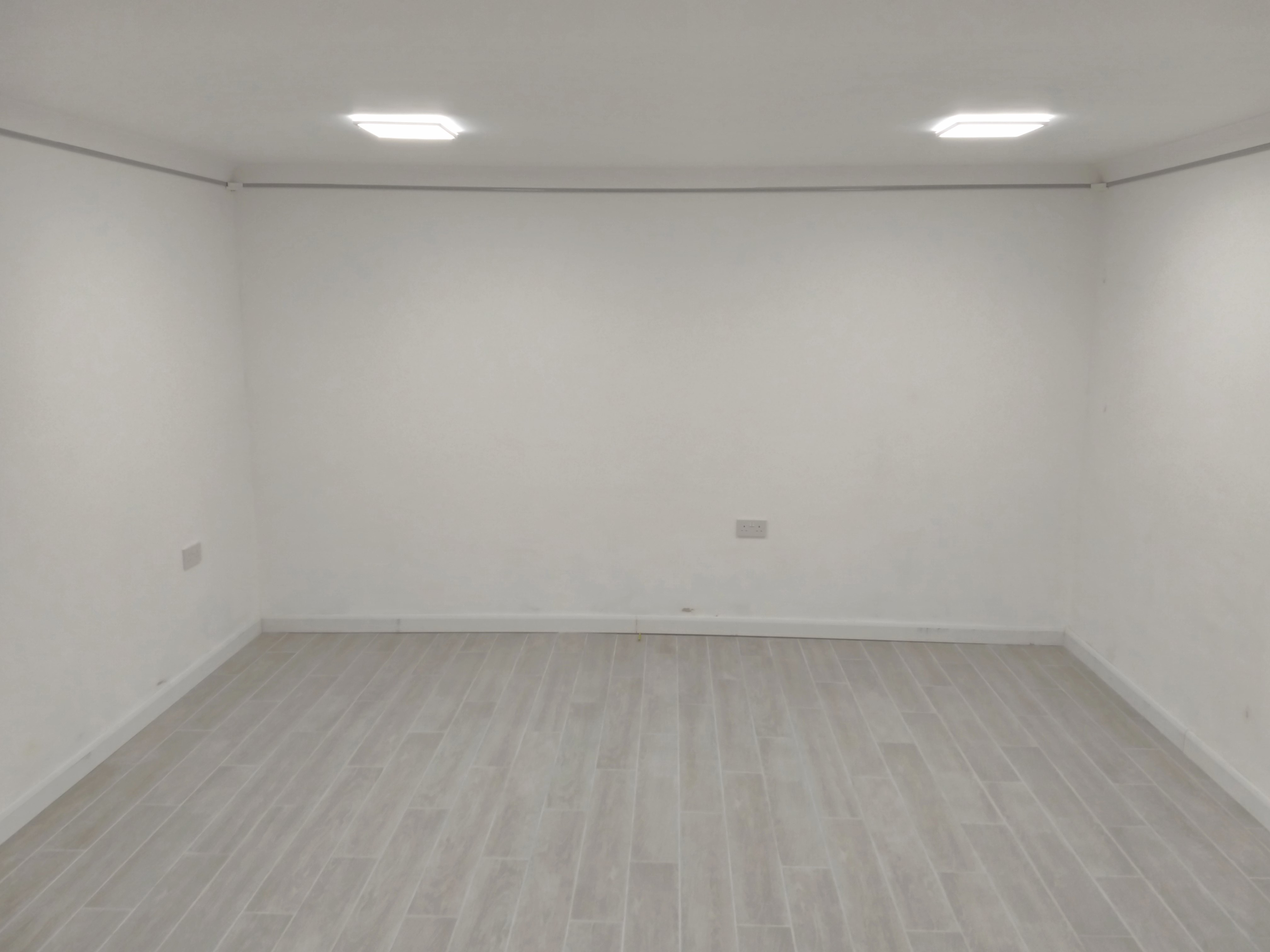
After
The finished product after all the work we’ve completed, from a similar viewpoint. Better photos near the end of the post. The goal was to have a finished “inside” style room we’d be comfortable in for our nerdy activities.
Now, let’s start from the beginning.
Preparing the Canvas
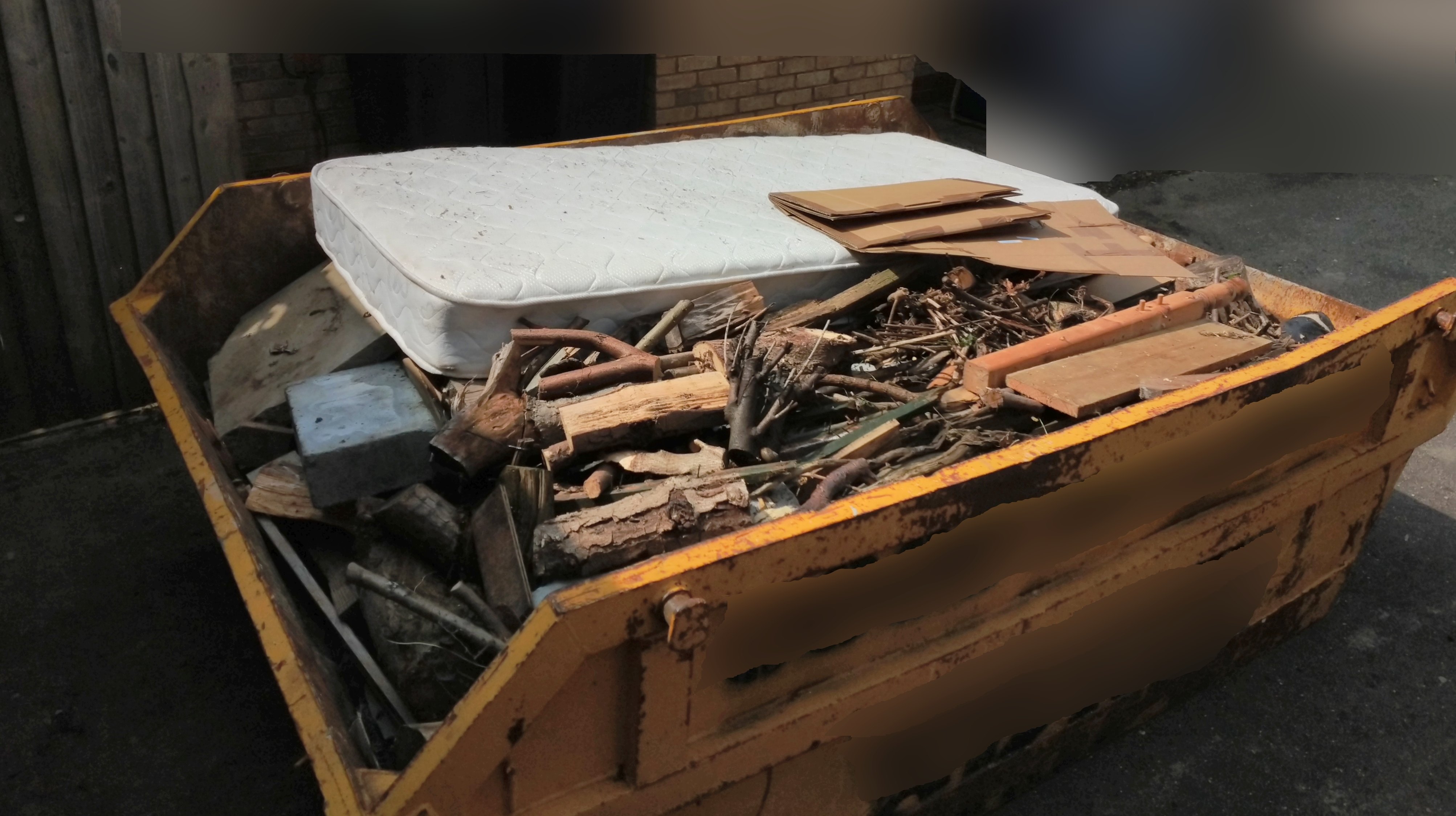
Despite the sellers’ good intentions, the items left in the garage weren’t of any use to us, so we started out by hiring a skip to clear it all out. Outside the garage were some more items to get rid of, so we did a pretty good job of filling a small skip.
We swept and vacuumed as well to get rid of a bunch of dust and smaller debris.

The existing concrete floor was far from flat, measuring a difference of up to 8cm front to back. We decided this needed levelling out before we could do anything with it.
Creating a Level Floor Base
We settled on creating a division between the front of the garage (where the gates are) and the large back section. The front section only had to be wide enough to allow the pivoting gates to fully open (about 1.4 metres). This provides ample storage space for bicycles and some garden equipment, while sectioning the rest off for a clean room.
We ordered some lumber and mounted it to the floor, both to contain the screed floor, and as a base for the dividing wall.
I didn’t expect to be learning new things at this early point, but I spent a few drill bits on learning how to drill into concrete. As it turns out, it’s not as straightforward as drilling into wood where you just apply pressure and squeeze the trigger until you’re through. I did know to use the correct type of drill bit, but learned that you should apply pressure in reasonably short bursts of a few seconds at a time, otherwise you’ll end up overheating and ruining the drill bit.
We used 10cm-long concrete screws with Torx heads. It took a little while to realise a torque wrench was needed to drive these into the concrete, as a manual screwdriver didn’t quite cut it. An impact driver would also have been helpful at this point, but we only ended up buying one of these when the wooden framework got underway.
After we finished installing this lumber, Brittany applied caulk on the edges of the area for the new room. This would stop the flow of screed from seeping in underneath the wood.
After talking to a company that pours Screed, we learned we should prepare the existing floor with polyvinyl acetate (PVA) to stop it getting absorbed into the concrete. This left the floor a mossy green.

It was then time for the only part of this project we didn’t do ourselves: having the screed pumped in. A company aptly named Liquid Screed Pumping did what it says in their name, and it looked like this:
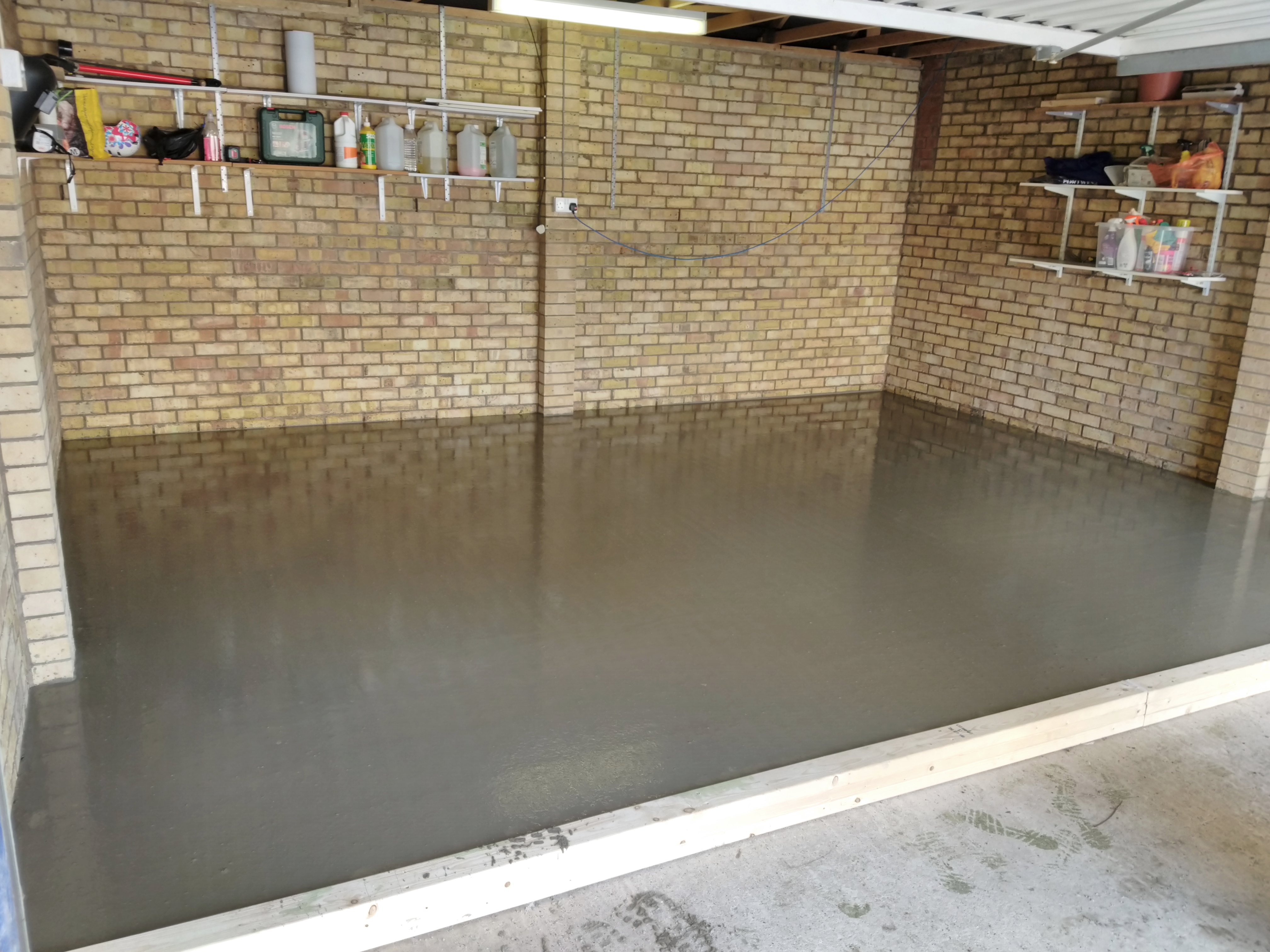
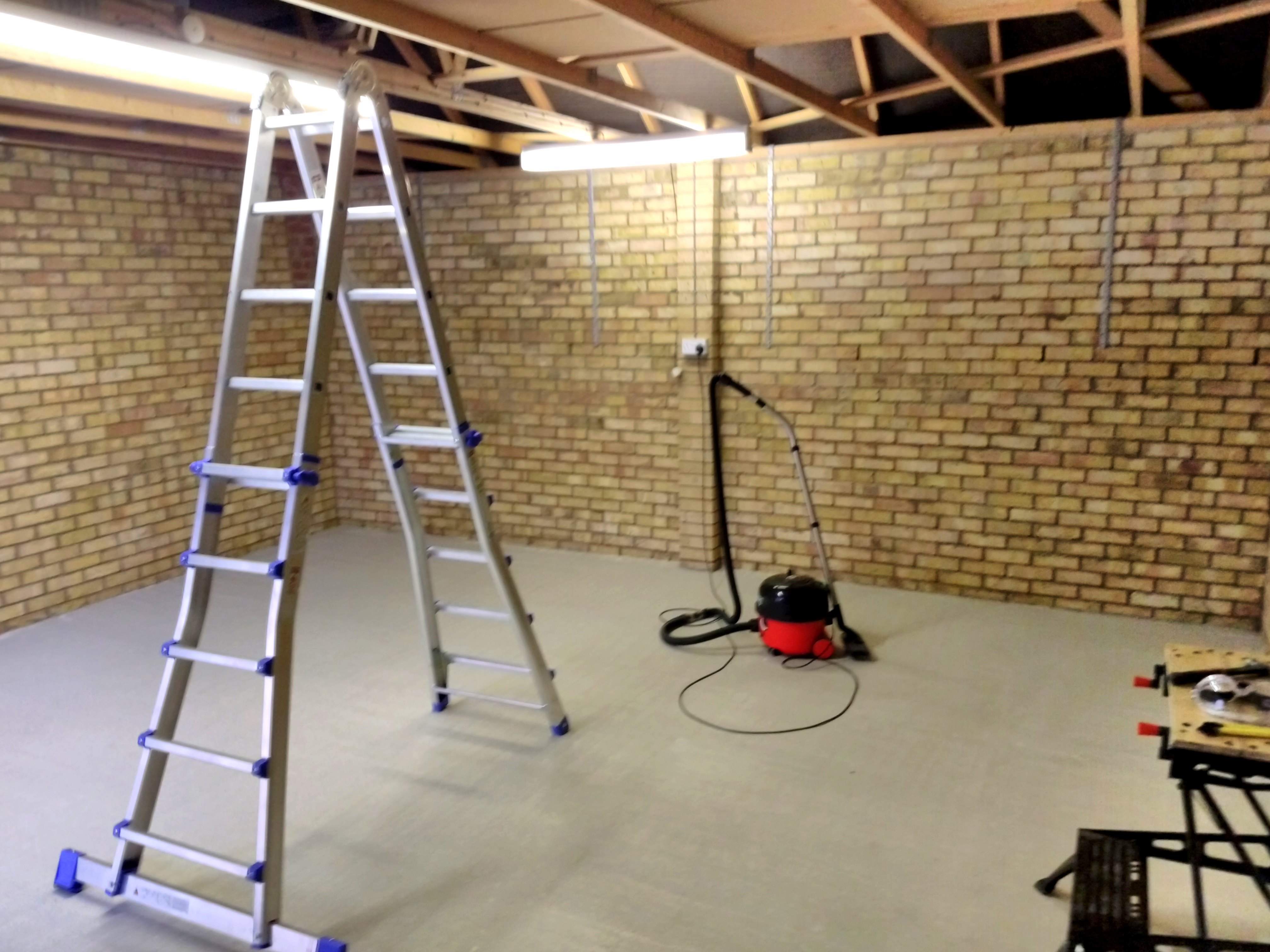
After about two weeks, it had adequately hardened, and we could start thinking about some other jobs.
Initial Electrical Work
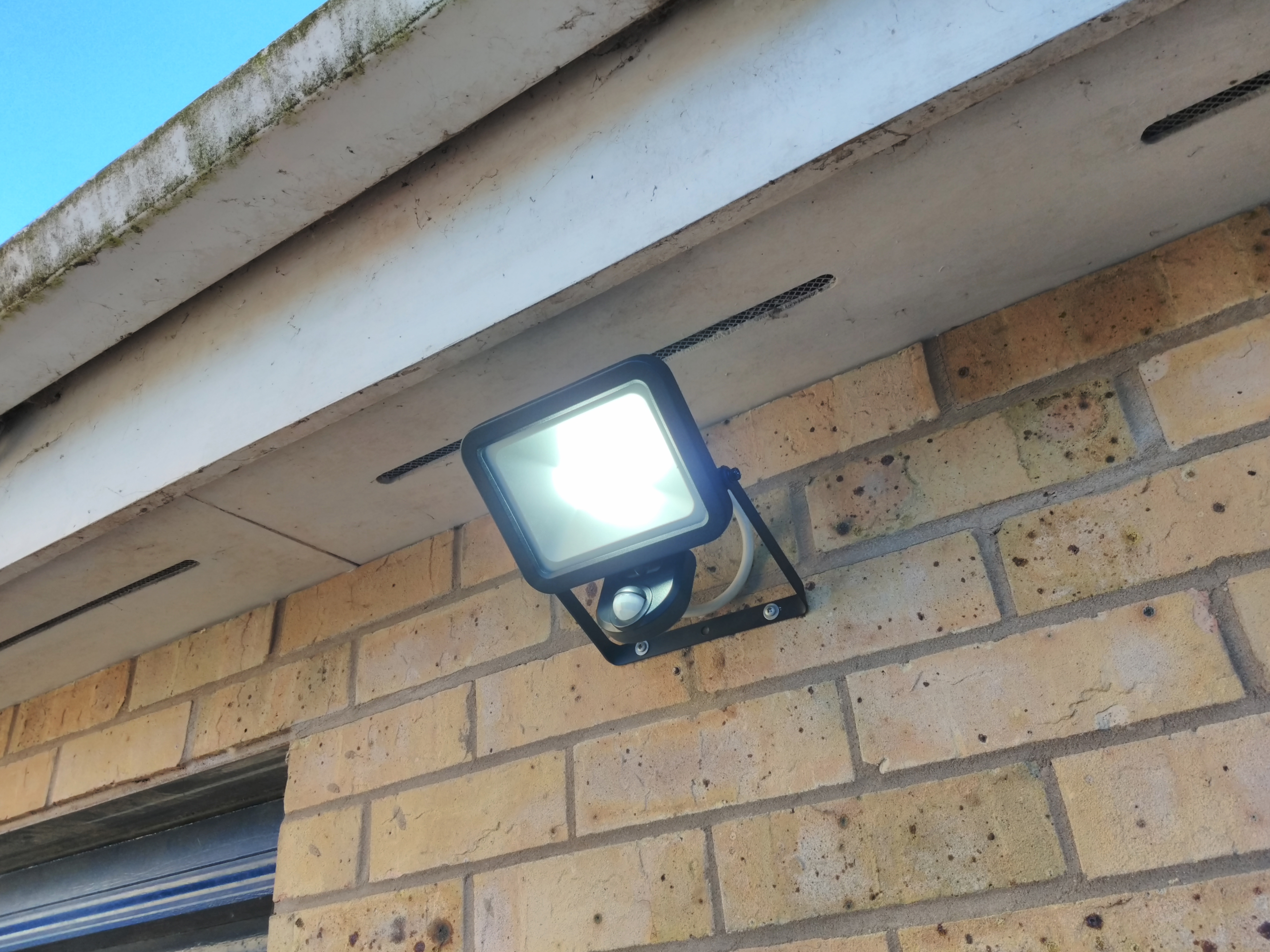
In late August, I began planning the electrical installation. All the existing light fixtures, sockets, and switches would go, to be replaced with new ones, in different places. There was no wooden framework for the walls yet, so, I figured I’d start out by replacing the broken floodlight at the front. Once the dividing wall was up we would require separate lighting in the front section, so I installed a simple bulb between the garage gates.
This energy-efficient LED floodlight replaced an older (I think) ~250 Watt halogen one.
A simple LED bulb lights up the front section.
There was another floodlight at the back of the garage, which I replaced with an LED one identical to the one at the front.
Inside, I removed the existing sockets and their cabling from the rear area. I installed one new double socket in the front section, connected via a junction box that would later connect all the sockets for the room to the circuit. This would be the only one in the garage until all the new walls got finished up.
While doing this, I quickly learned that hammering cable clips into brick (or mortar) is not easy– I very often ended up bending the nails. I ended up drilling small pilot holes with a masonry drill before hammering the clips into them. This took a lot more work, but all but eliminated the chances of bending the nails.
To remove cable clips from wooden joists, I used a pair of old side cutters to get behind the plastic. When you get behind it, you can use either the side cutters or the claw of a hammer to pull the clip out the rest of the way.
Constructing the Framework
On September 7th and 8th, we got some deliveries, culminating in this giant heap of fun.
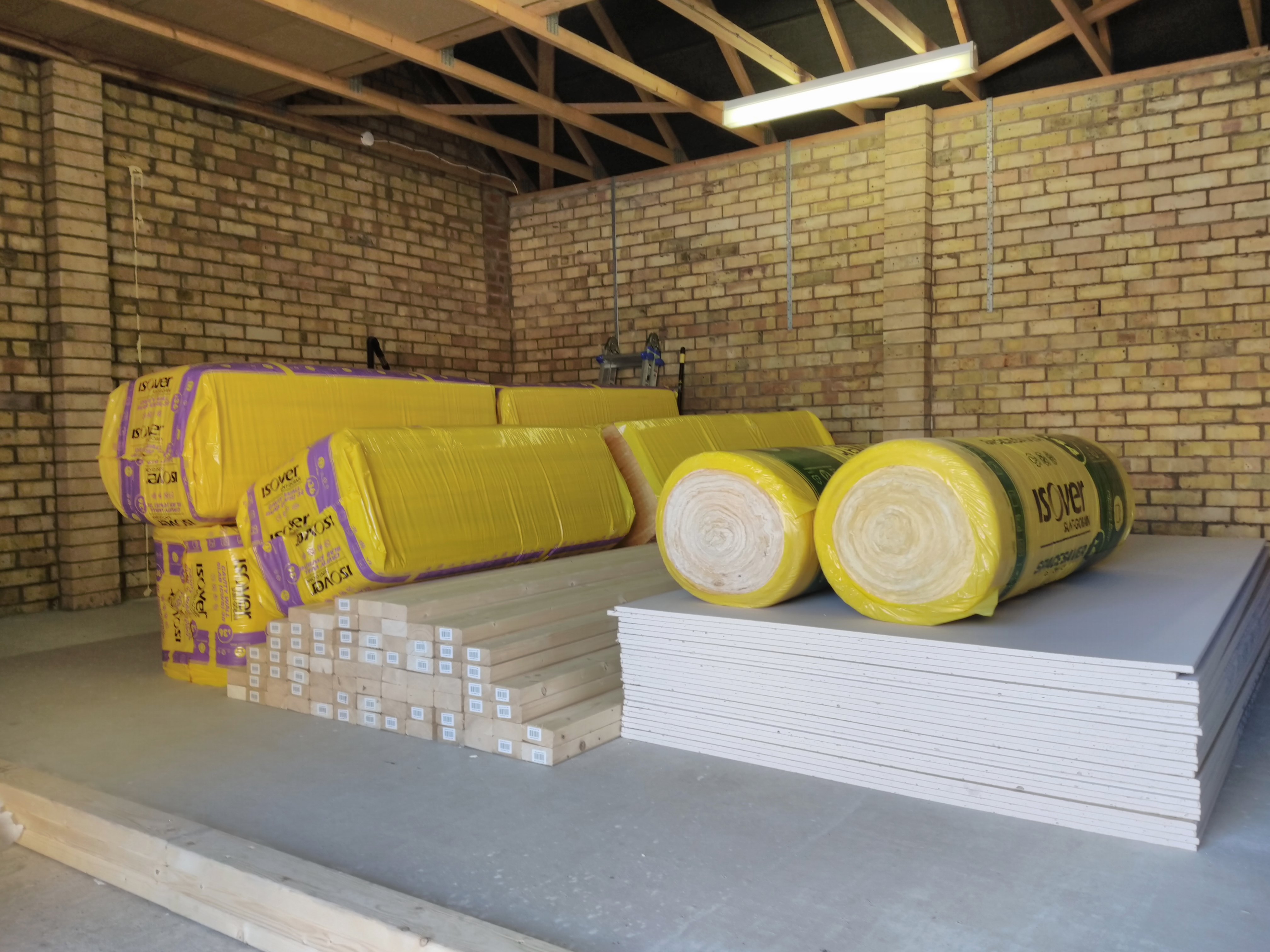
We probably should’ve held off ordering some of these materials until we were ready to use them. The packs of insulation quickly moved to our conservatory, which has been a dumping ground for tools, materials, and things that’d be in the way elsewhere throughout this project. The stack of plasterboard remained in the garage and acted as a table for a long while.
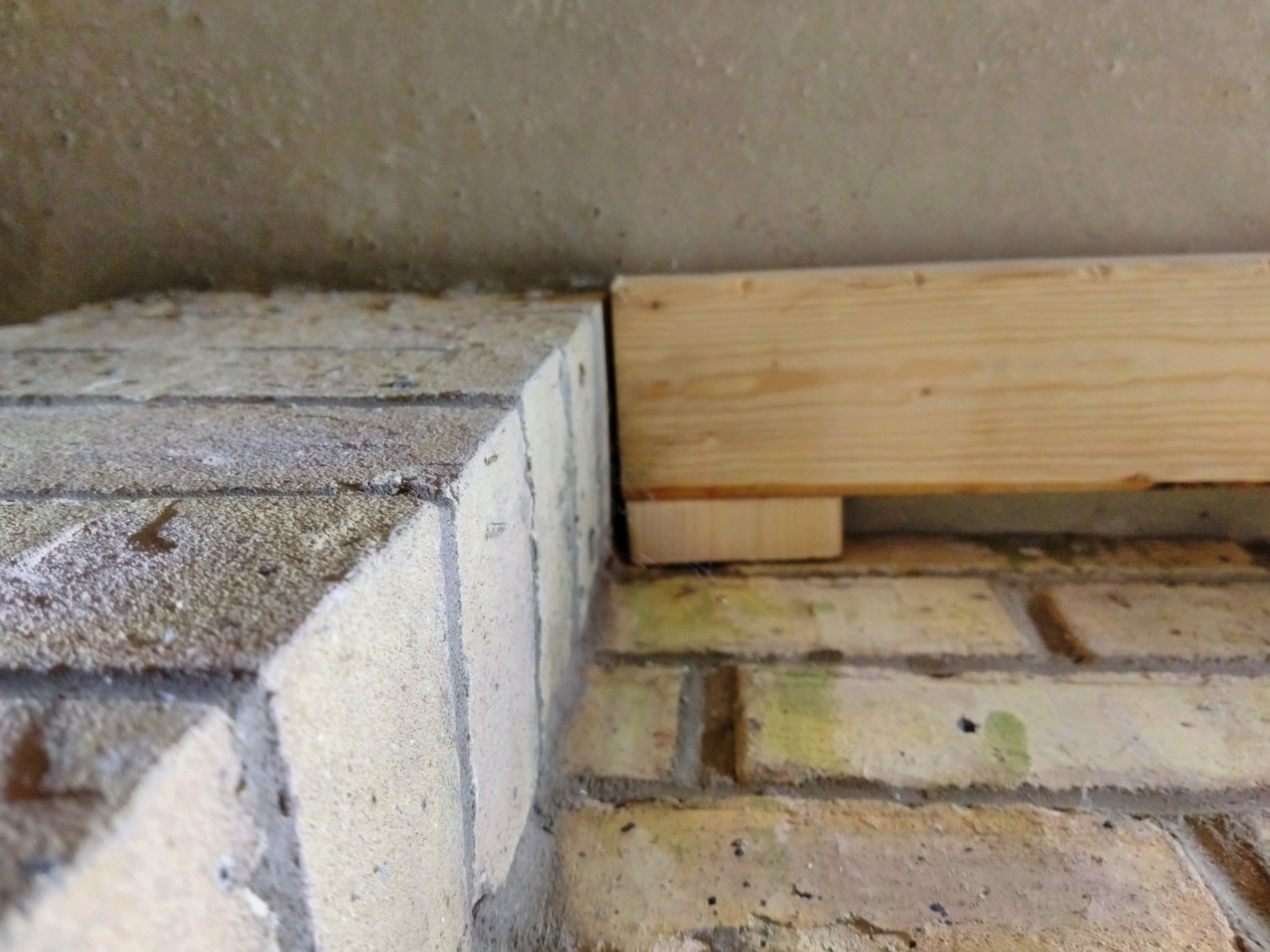
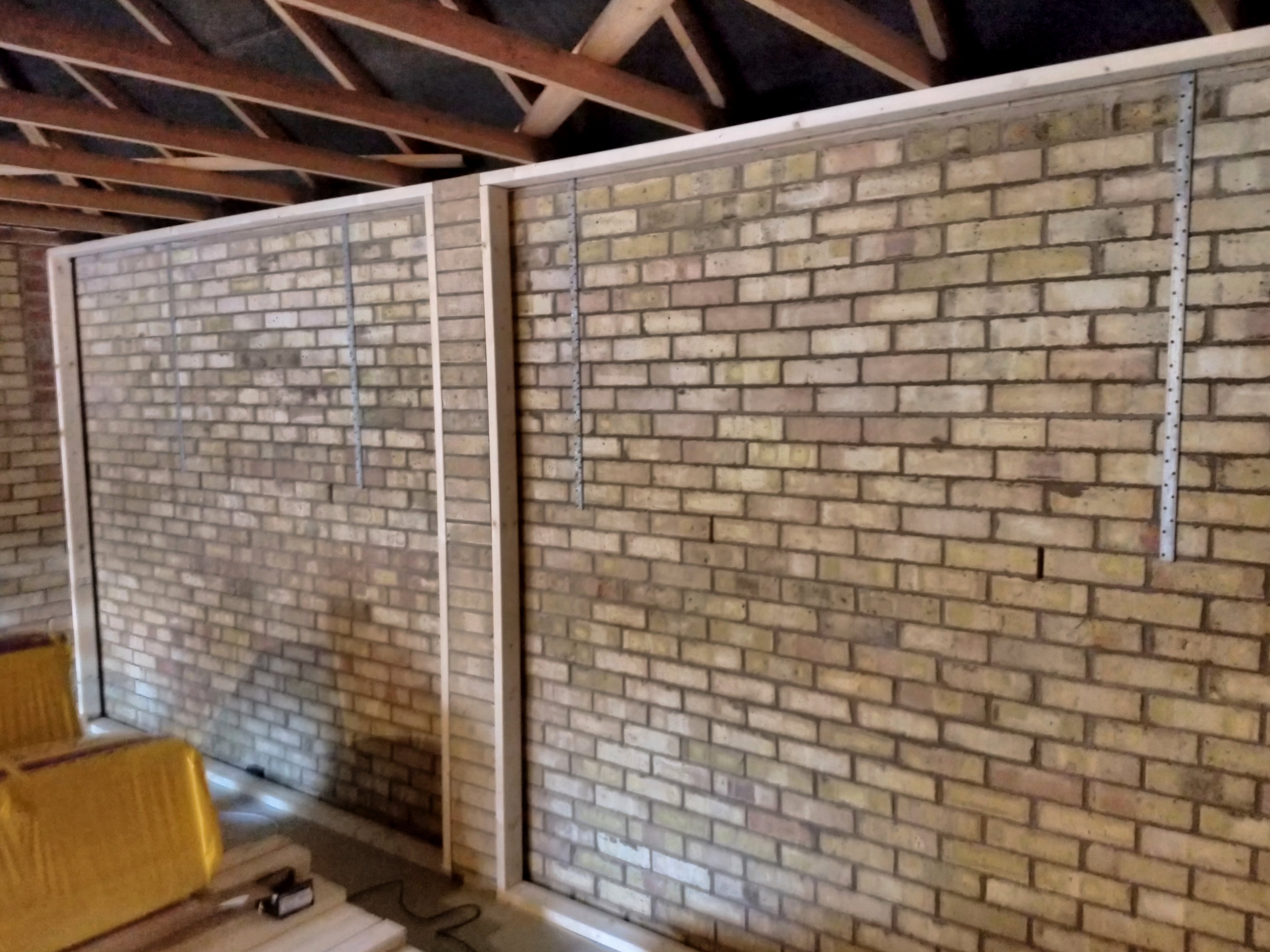
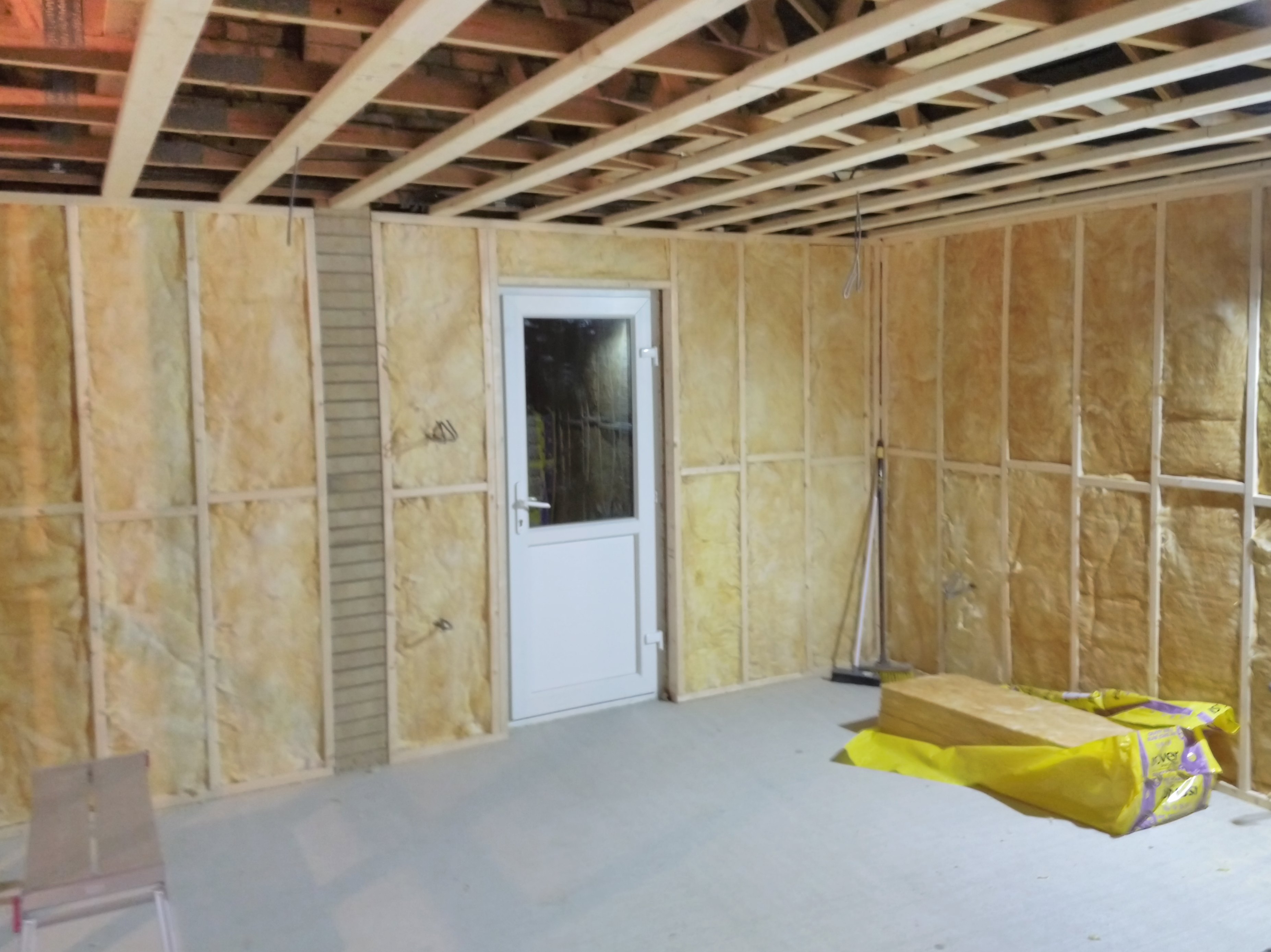
We started by building the outer frames against the walls. On each of the three walls, there’s a single-brick-wide column, supposedly for reinforcement. We wanted to keep our walls simple, stretching from one end to the other without features. Accomplishing this started by building the framework to allow the plasterboard to bridge across these columns. I ended up making some 3D printed blocks (not shown) to help keep the right margin between the lumber and the brick wall before fixing to the floor or brick.
The framework build involved many cuts, and I only had a hand-held circular saw for it, so I built a jig to get the offset from the edge of the saw to the cutting line right. This saved some time, and served a double function as a right angle. A proper mitre saw could’ve saved more time here, but cutting the lumber was definitely not the time bottleneck.
Back to the build– I first focused on installing all the pieces that had to be fixed onto the concrete floor and masonry (bricks) because those form the basic framing for everything else to attach to… and were the hardest to do.
To install these, I:
- Measured the required length
- Cut a piece of lumber to size
- Held it in place either by clamping it with F-clamps, or by getting a nice press-fit so it held itself in place
- Drilled through the wood where I wanted the screws, allowing it to mark the brick or concrete beyond
- Removed the lumber
- Drilled into the brickwork or concrete with a masonry drill bit (with a separate, mains-powered hammer drill)
- Replaced the lumber
- Screwed in some concrete screws using a ratchet wrench with Torx bit adapter
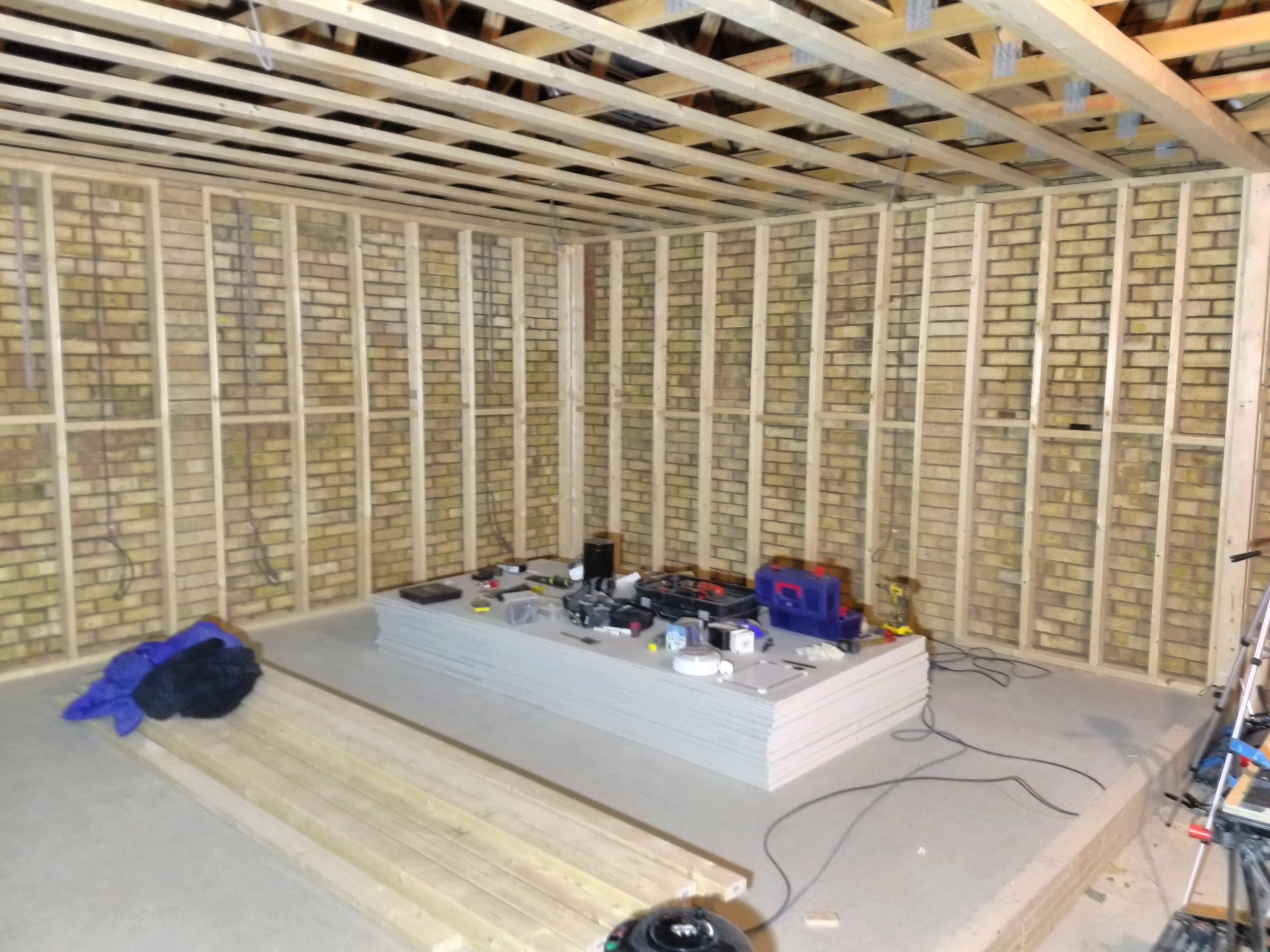
Around the same time I installed ceiling beams perpendicular to the existing joists. These are what we would lay the ceiling insulation on, and to which we’d attach the ceiling plaster boards.
Brittany had the great idea to get ratchet straps to install these ceiling beams, and they were a great help. I’d make a loop around two ceiling joists near the ends of a beam, then lift in the beam into the loops, and tightened the ratchet straps while moving the beam more closely into its final position. I then drilled pilot holes and screwed them permanently in place.
It is around this time a good friend made me aware of the existence of impact drivers. They are powered screwdrivers that use small rotational impacts to apply much more torque on a screw than ordinary powered screwdriver can. They are noisy, but they drive a screw fully into wood and countersink it, without any remaining manual tightening. It made a world of difference for the remaining framework build, and later, the plasterboard installation.

After completing the ceiling beams and outer framework, it was time to fill in the open spaces. This provided points to attach the plasterboard, and generally made the whole thing sturdy. We measured the spacing between vertical beams to suit the size of our plaster boards. The horizontal bits in the middle, connecting them, are staggered to allow drilling and screwing into their ends. Using a laser level on a tripod (another very useful tool), we easily got these beams nicely vertical, and the connecting pieces very level throughout the room.
Installing the vertical joists that weren’t attached to the brick was a different process, called “toenailing”. I put it in quotes because I ended up using screws instead, but the basic idea is similar. You hold the joist in place, then put screws through the other side of the vertical joist toward the one on bottom (or top) from the other side.
The process I ended up using:
- Mark out location of the vertical joist on the horizontal ones, top and bottom (with help from laser level)
- Screw a piece of scrap wood (I’ll call them positioning blocks) right at the edge of where you want the beam to go, on opposing sides at the top and bottom
- Cut a piece of lumber to length
- Line it up against the positioning blocks
- If needed, clamp the beam in place with f-clamps. If the size is just right, it can also press-fit
- Using a long drill bit, drill pilot holes diagonally near the top and bottom, trying not to come through the other side of the beam
- Drive a 10 centimetre screw through
- Repeat on the other sides, top and bottom.
- Remove positioning blocks
Sadly, I didn’t take any good photos to better demonstrate this process. Someone more skilled might probably accomplish this without the pilot holes, but I found it necessary to get the job done reliably.
Further Electrical Cabling
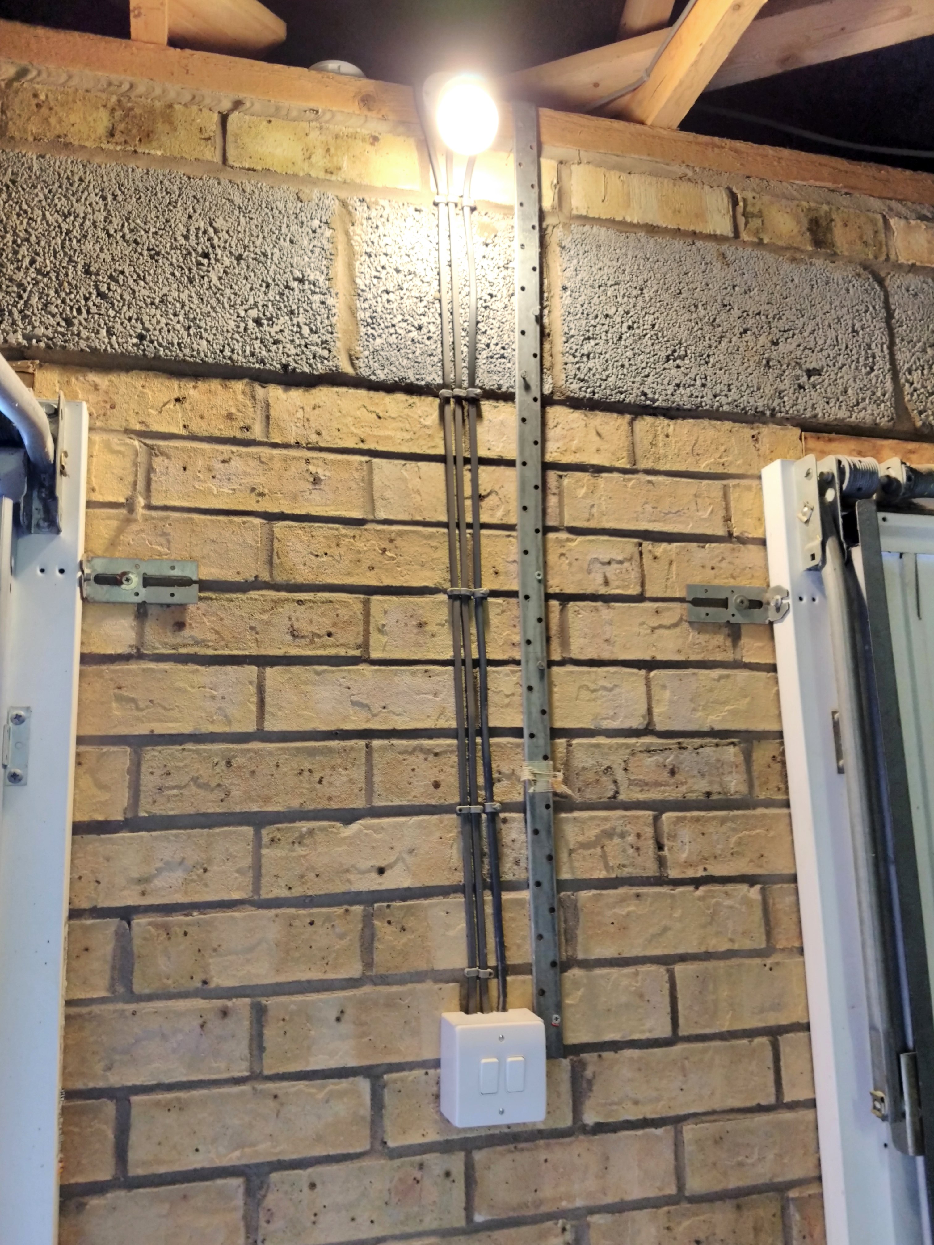
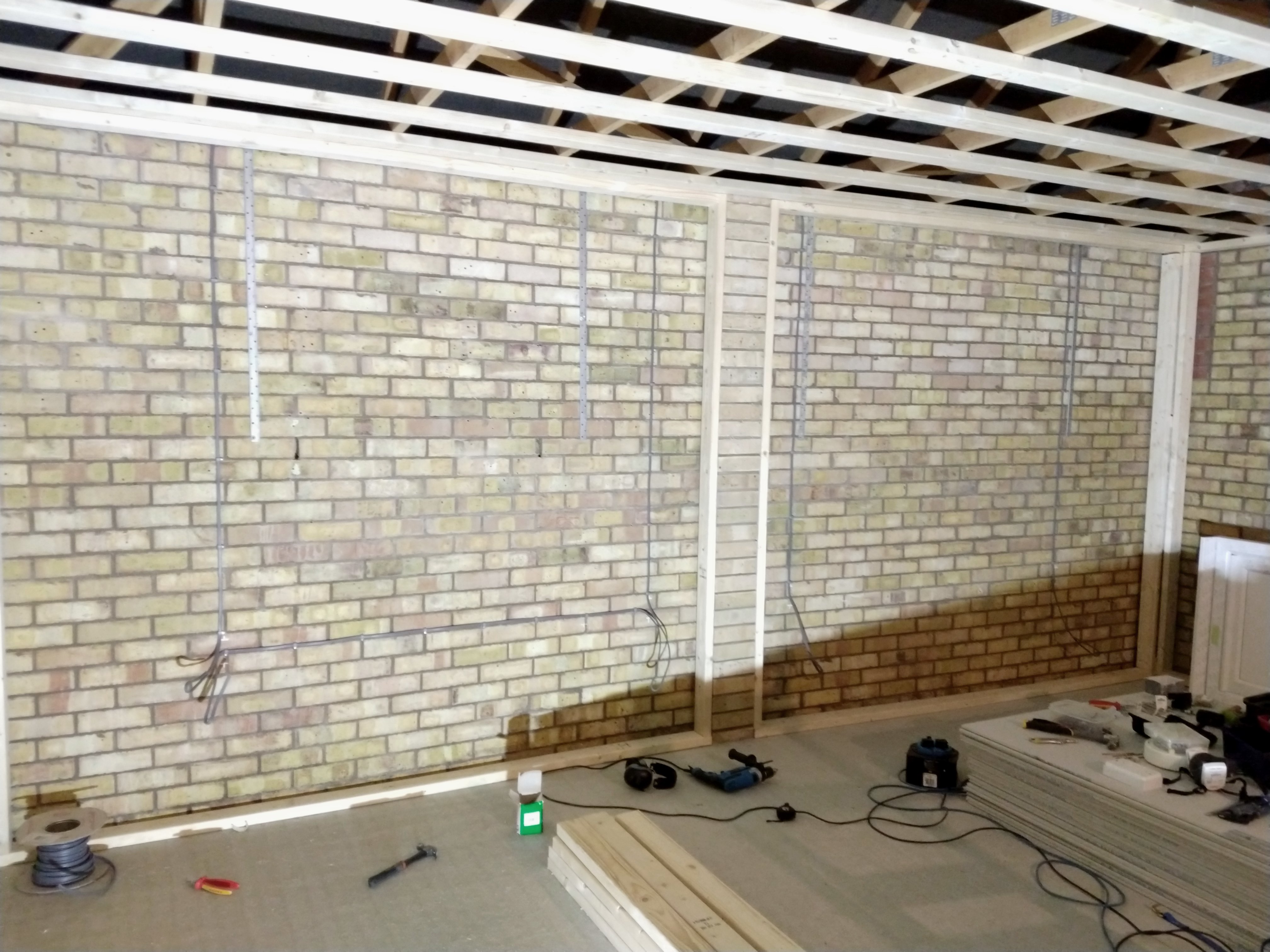
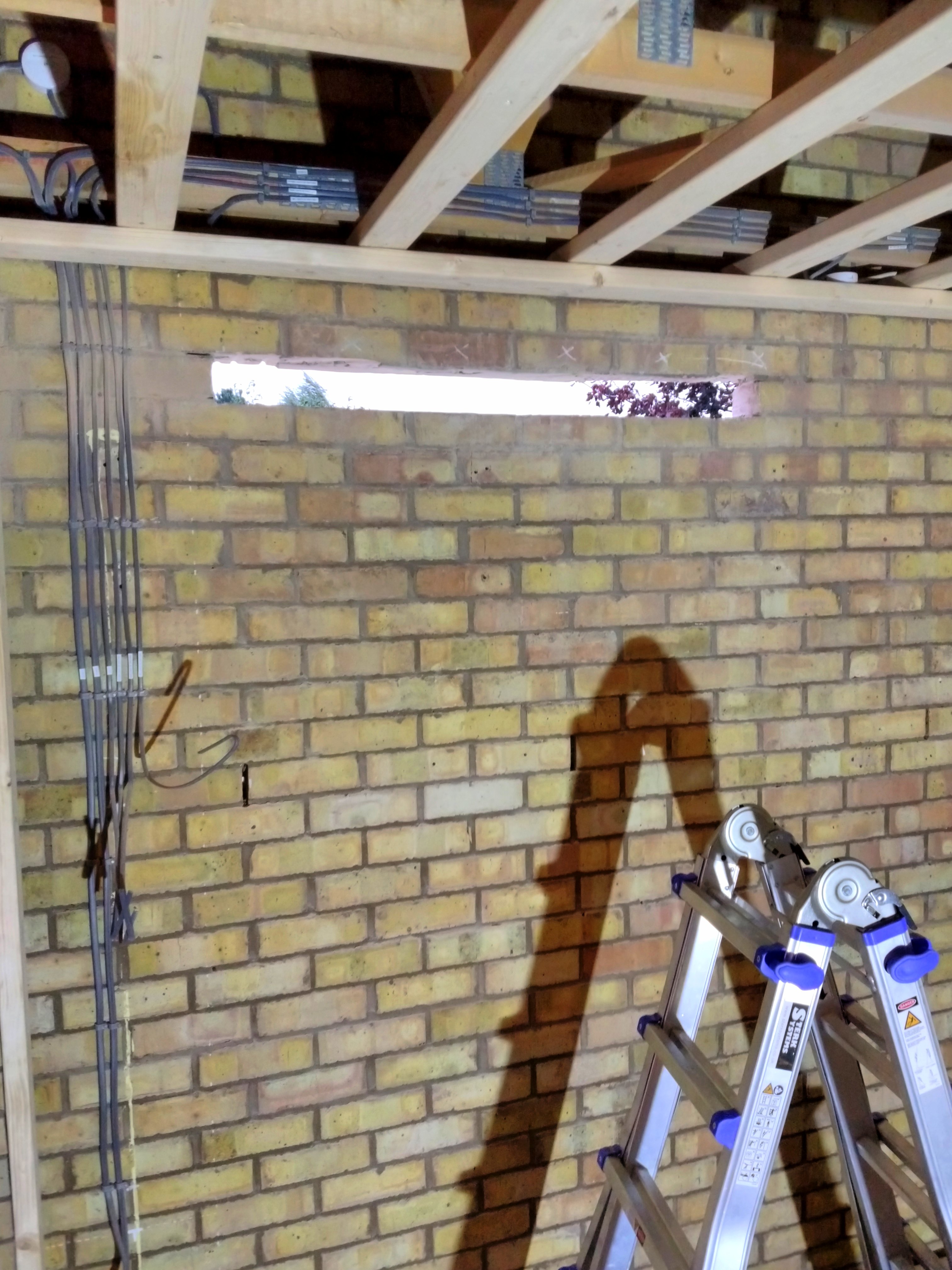
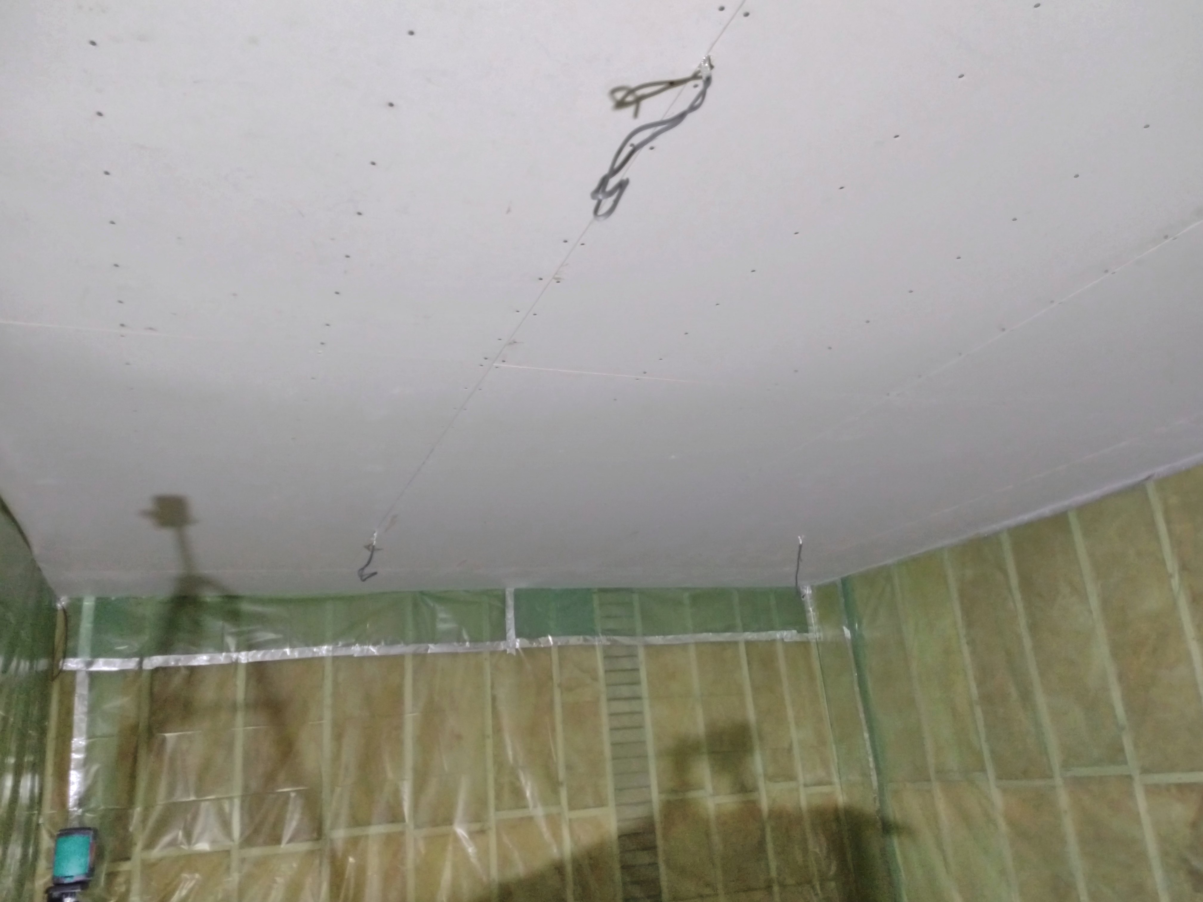
During the framework build, I installed all the electrical cabling. Following building codes, I ensured cables were installed only vertically and horizontally, in line with where the hardware connected to them end up. This ensures that when all you can see is sockets and switches, you have a good idea of where to avoid drilling. That said, the cable is attached to the bricks–some 10 centimetres back from the finished wall–so hitting a cable is unlikely.
I planned the hardware locations based on the edges of plaster boards, ensuring there’s enough clearance for the back boxes between beams. On the rear wall, there would be 4 double sockets, and another one on both the left and right walls; 6 double sockets in all.
For the lighting, I planned two sources of lighting:
- Main lighting: 4 neutral white LED fixtures distributed over the ceiling
- Secondary, mood lighting: An RGB LED strip around the top edges of the room, all the way around
To start, I ran the main lighting cabling from the left wall, where the light switches would go, along one of the existing joists to the back of the garage, and from there along other joists to where the lights will be.
I decided to route via the back of the garage instead of going through or over the joists; through would weaken them structurally, while over would get in the way of floorboards we’d install in the loft later. This approach required a bit more cable, but I figured the practical concerns outweighed the slight material savings.
It’s hard to take a good photo of something as small as a few cables spaced far apart, but here’s an attempt:

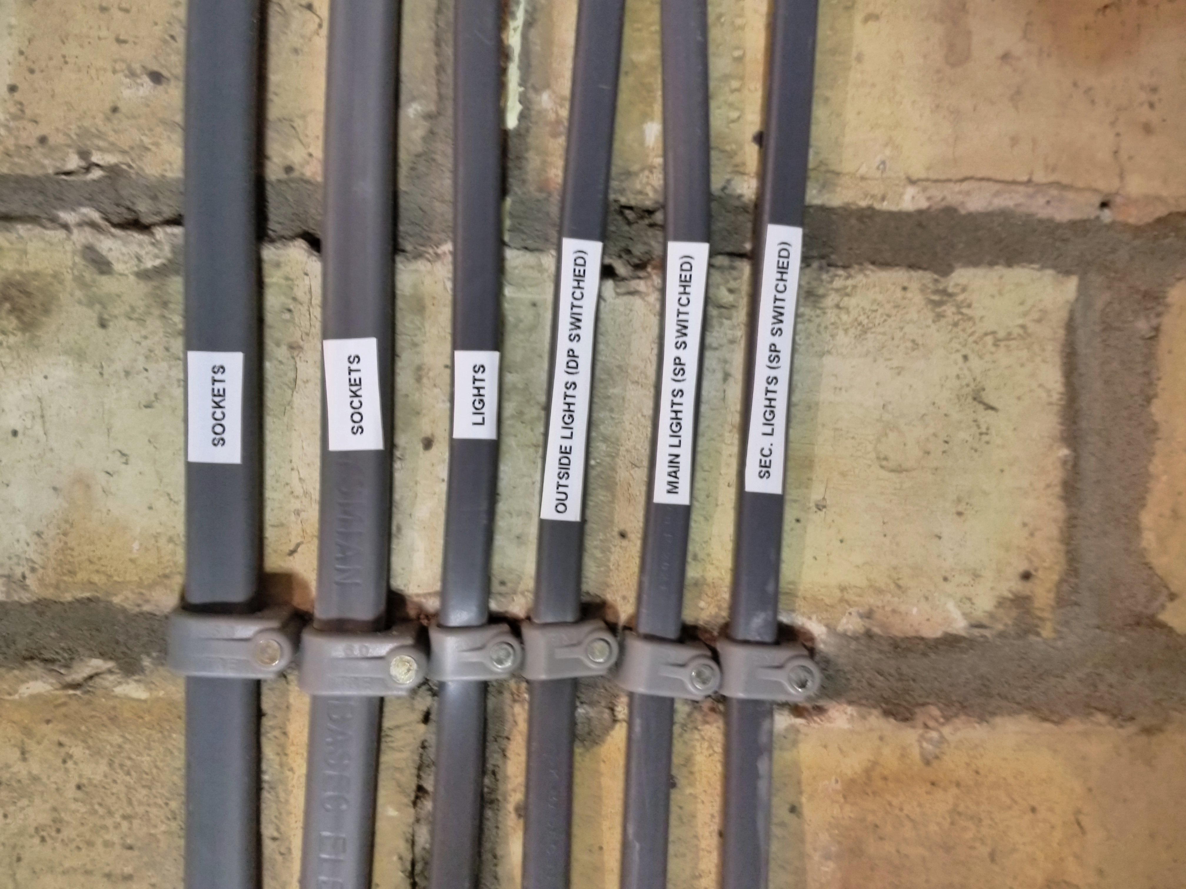
The light switch is right above a double socket, so the cabling got a bit busy over there. I added labels to keep track of what’s what. In total, there are 3 switches here: Outside lights, secondary lights, and main lights.
“DP Switched” here means “Double pole switched”: both the “live” and “neutral” wire are interrupted when switched off. “SP Switched” only interrupts the “live” wire, leaving the neutral wire connected. Double pole switching is important for outside devices, ensuring mains power is fully isolated when switched off.
For the secondary lighting, I calculated I’d require a powerful 5V power supply on each corner of the room to ensure consistent power delivery. At these low voltages, the length of the strip presents a considerable voltage drop, leading to incorrect colours being shown and other malfunctioning behaviour. Providing 5V at each corner prevents this voltage drop from getting too significant.
I ran cabling to a junction box on each corner, and then attached a Meanwell power supply directly to the bricks above the ceiling, and wired it into the junction box. I extended the low voltage wires a bit to reach far enough through the wooden framework.
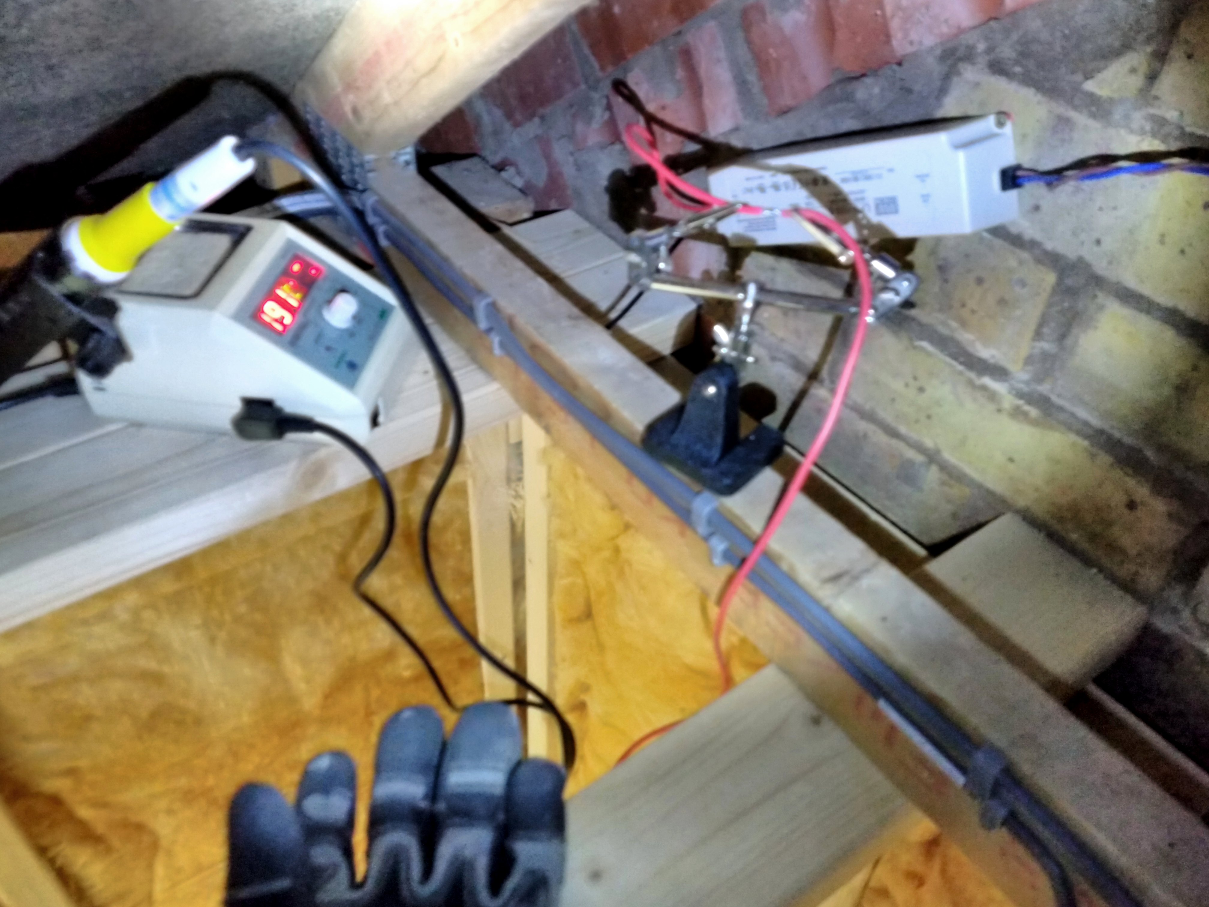
I didn’t take any good photos of this setup, but I have this one. Here I’m working in a tight corner under the roof, standing on a ladder, soldering extensions to the low voltage wires. In retrospect, it would’ve been far easier to extend the cables at the comfort of a table, but I only realised that extensions were needed when the power supplies were already mounted to the wall.
Side Door
One of our earliest decisions about the garage was to add a side door to the wall facing our patio. We definitely didn’t want to swing up the garage gate every time we wanted to spend time in there. Given how we ended up separating the room area from the front of the garage, that approach would have required a door in the new dividing wall anyway.
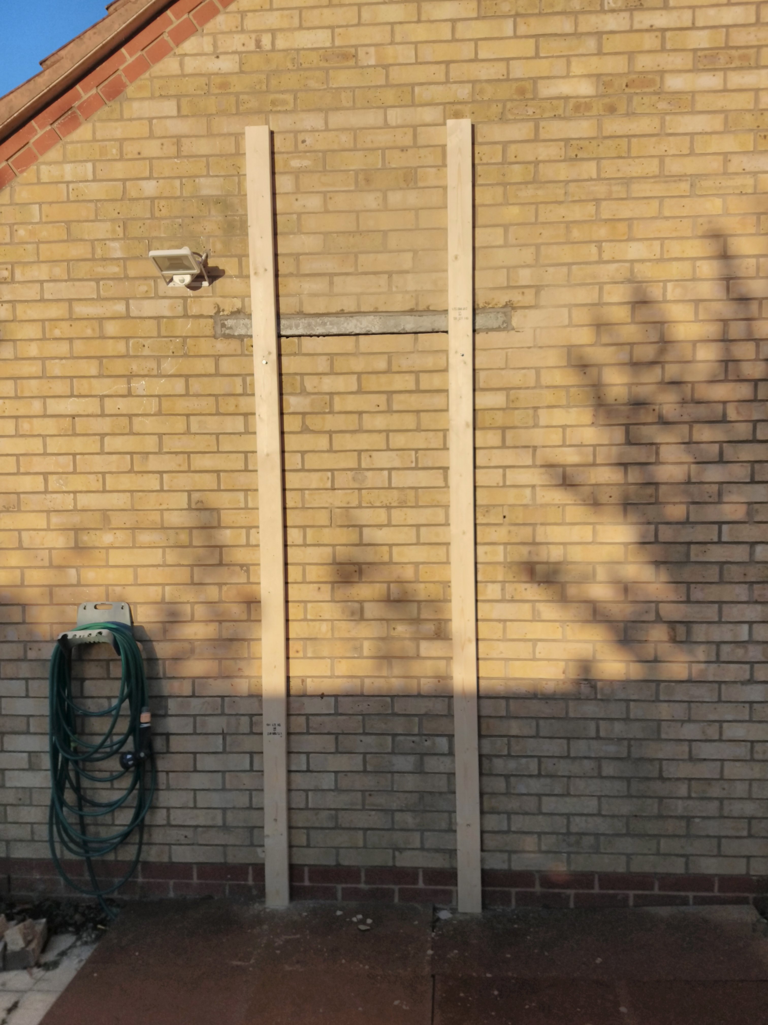
We ordered an outside door online, as you do, and made sure to do our research. This one was by far the most daunting of the tasks we did ourselves. It took around 2 months for the door to arrive, during which time we worked on the framework, electrics, etc.
We bought an angle grinder, a concrete lintel, some mortar mix, and went to work. We first cut the lintel to size to match the length of a number of bricks, then decided on the exact position for the door and marked which bricks that we’d remove.
Suited up with safety goggles, ear muffs, a respirator mask, and sturdy gloves, we cut through the mortar with the angle grinder, and finished off the short edges with a hammer drill. We then carefully pushed out the bricks, leaving a lintel-sized gap.
Then, we moved the lintel in position, and used shims to be vertically centred in the opening, leaving a gap to fill in with new mortar (except below it where the door would go). We used a laser level to ensure it was as flat as it could be.

After the mortar around the lintel had set, we set up for the big scary job: cutting a door-sized hole in a brick wall. I screwed two pieces of lumber (from our stack for the framework build) onto the wall, aligned with the help of the laser level. This would make dragging the angle grinder in a straight line much easier.
I did the same on the inside, since we needed to cut both from the outside and inside to get all the way through the brick.
While cutting, I had to stop several times to clean my safety goggles; they kept getting coated in dust. I also regularly adjusted the angle grinder handle position, etc. It was a pretty scary task even with all the safety precautions, and I was glad to be done with it.
Once through on both sides, the fun part began: pushing all the bricks out of the hole. I laid out some old floorboards to catch any falling bricks, protecting our patio tiles.
We bought a beefy hammer drill to make this job easier. Essentially it acts like a chisel (not rotating), getting hit many times a second. One of us hammered away at the top row from the inside, and the other removed loosened bricks and stacked them aside. This made it quick work; soon it looked like this:
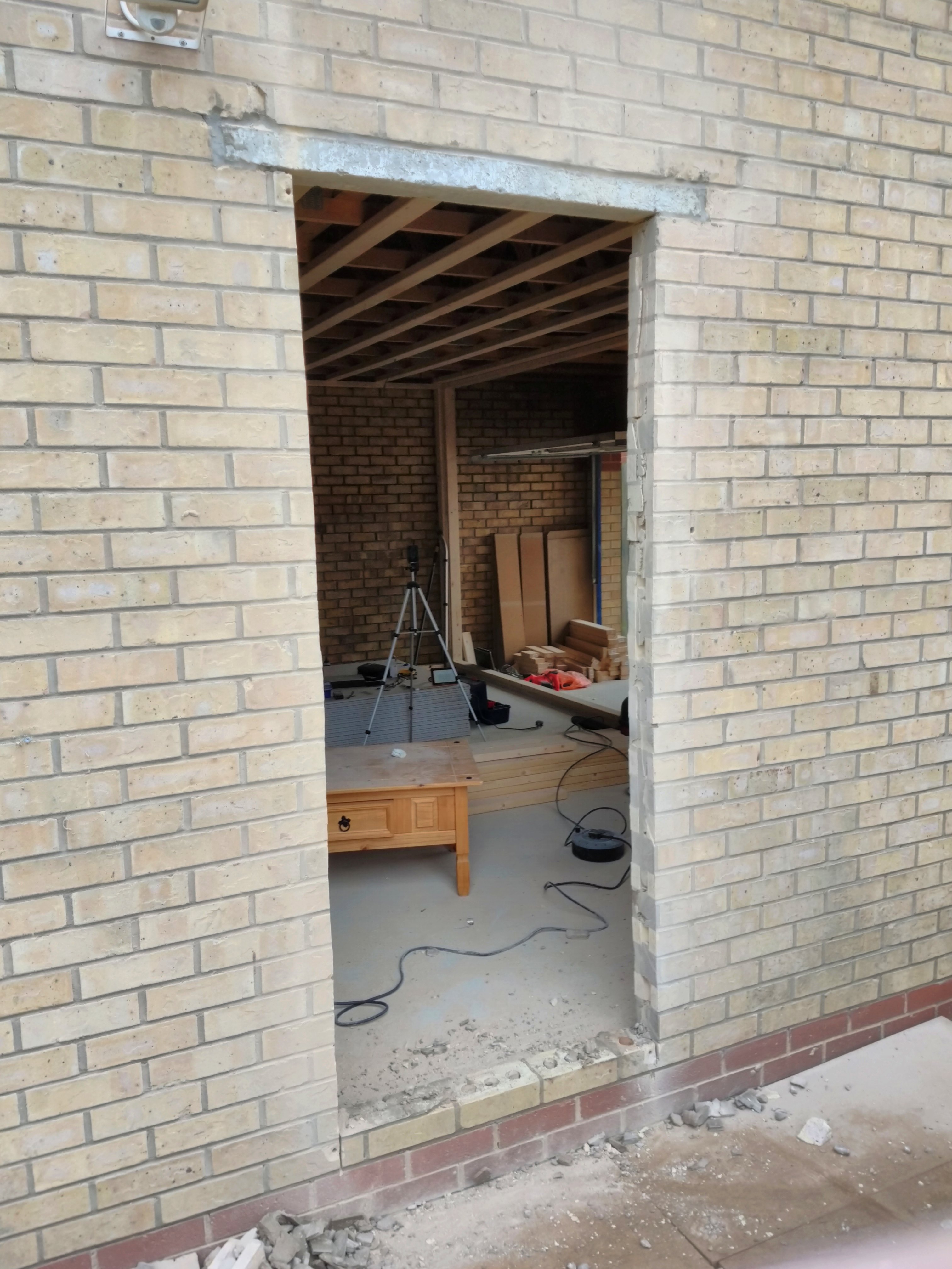
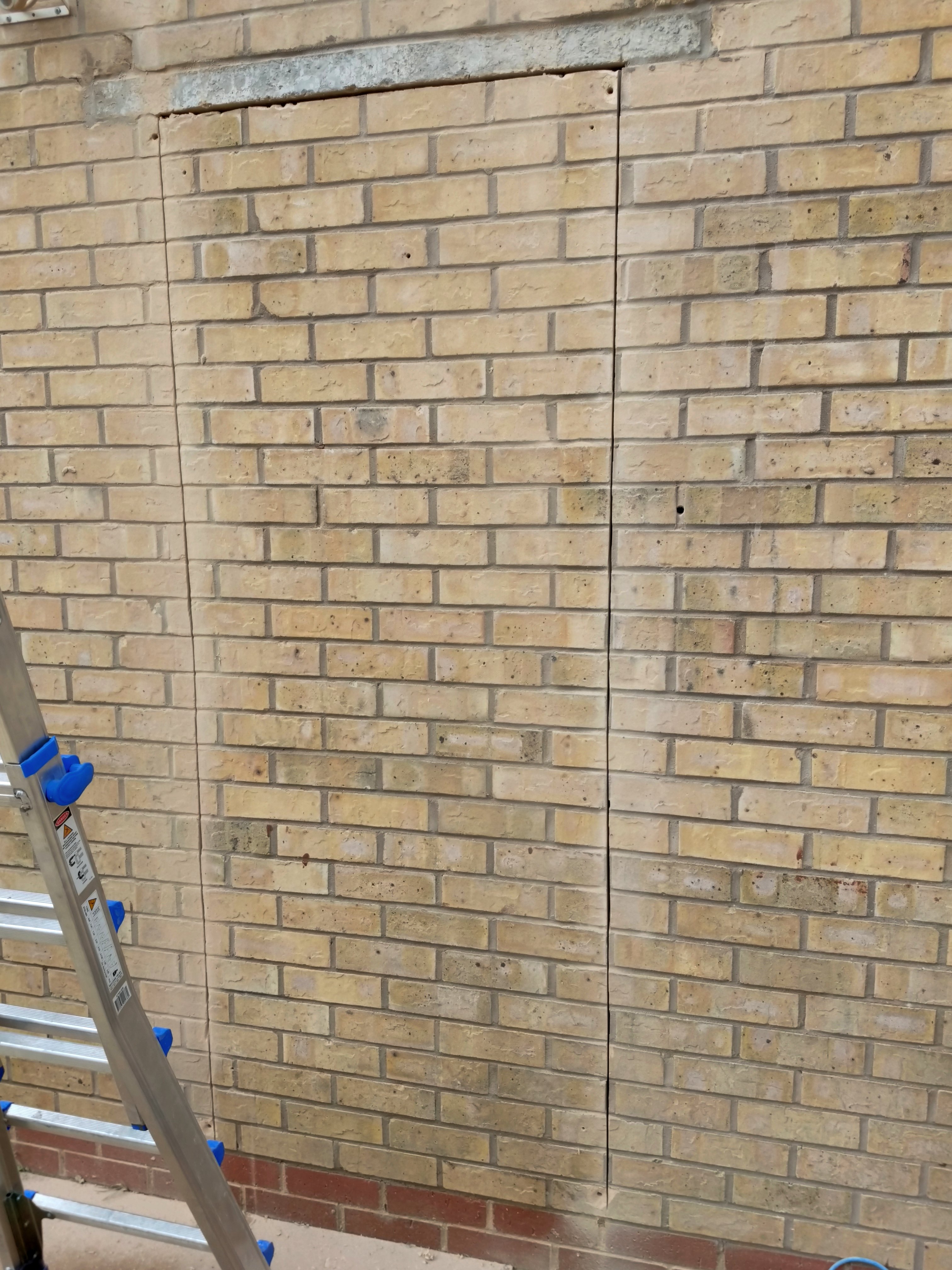
The inside and outside cuts didn’t line up perfectly, being up to around a centimetre off in some places. We worried about this a little at first, but we learned that in construction, there is always a solution or cover-up for inaccurate work.
The door we bought came “pre-hung” in its frame, likely saving a lot of adjustment work getting it to close properly. That said, between the two of us, it was very difficult to get it lifted into position– the thing is very heavy and unwieldy. We had to take the whole assembly out of the clearing 2 or 3 times to re-evaluate. At one point we decided we’d have to get the door removed from the frame, but we failed to get it off its hinges. Eventually I ended up holding onto the opened door, supporting it with my steel-tipped shoes, while Brittany drilled through the frame to get it attached to the brickwork.
After Brittany secured it enough, we jammed something else under the door so I could help with the rest of the fixing. We ensured the frame was attached straight with the help of a bunch of shims and the laser level before tightening the screws all the way. The shims ensured the frame didn’t get bent out of shape by the screws. Satisfied with that, we got to move on to installing the lock cylinder and the handle. By sunset, the door was finally installed, and looked like this (excuse the grainy photo):
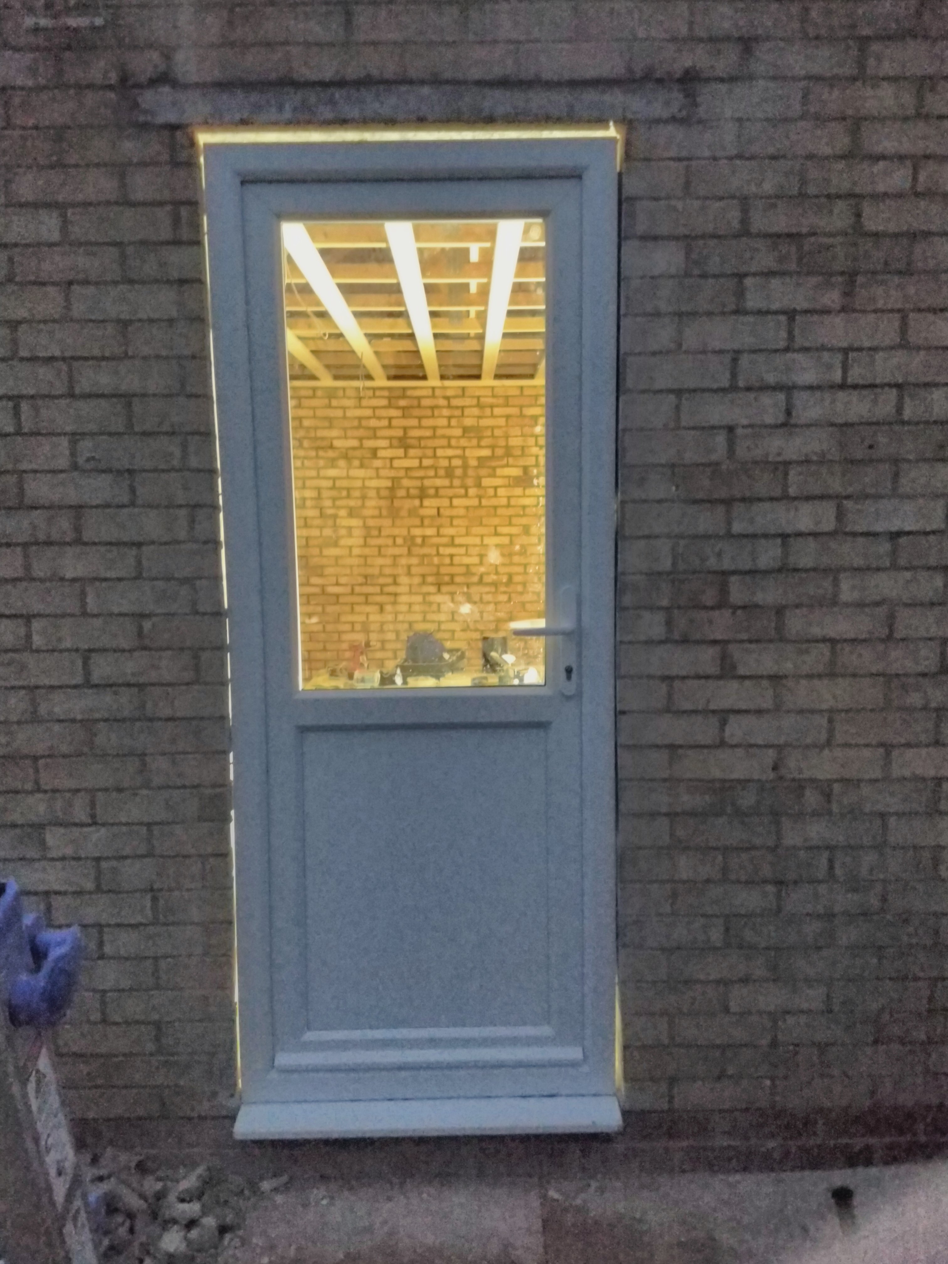
In this photo you can clearly see the imperfections; there are gaps around the doorframe. This was never going to be correct to the millimetre, so I guess being a centimetre off was not a big deal. The next day, we got a can of expanding foam, filling in all these gaps.
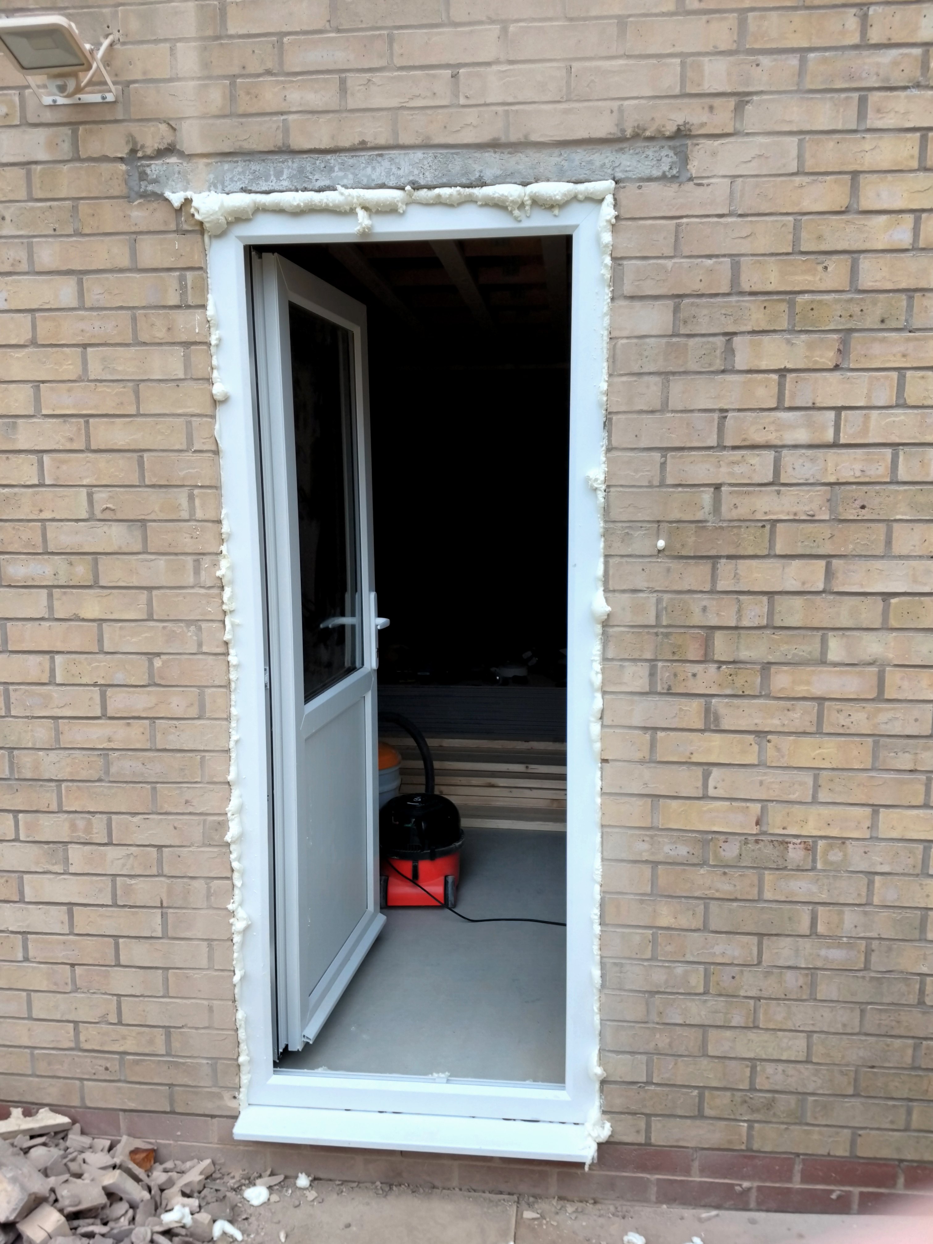
This stuff works wonders. We quickly learned it glues itself to anything it touches too; it was quite a job to clean up all the little spills all over the door. A plastic scraping tool helped.
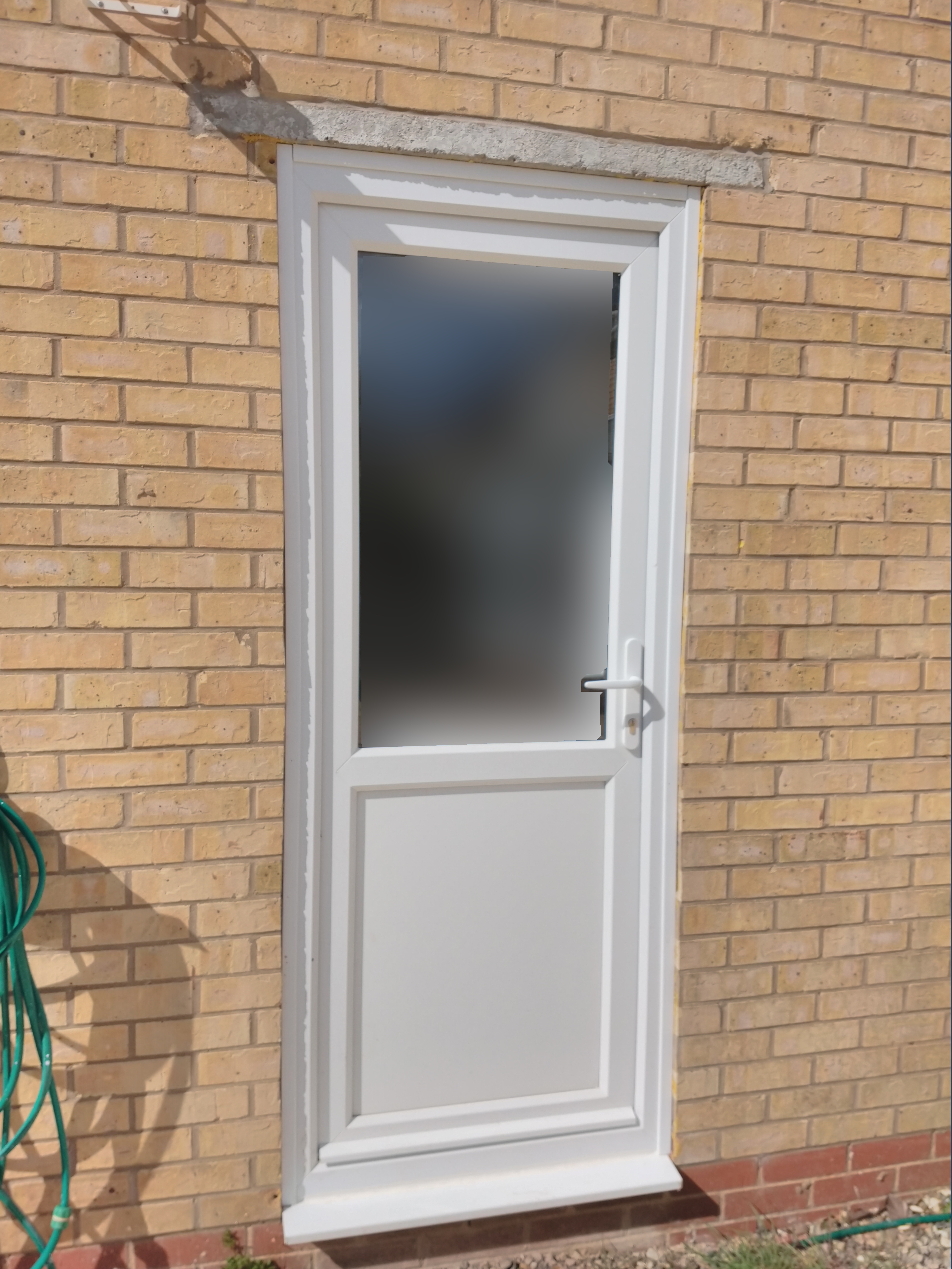
After the foam had dried enough, we cleaned up the excess with a knife and covered it up with a matching plastic trim, resulting in this:
Insulation
After completing the wooden framework including some additions around the door, we lugged the packs of glass wool insulation back into the garage and started stuffing it into the walls.
Glass wool fibre is quite a nuisance to get on your skin, in your eyes, or lungs, so we wore well-covering clothing, eye protection, respirators, and gloves.
Installing the insulation was fairly straight forward:
- Get a slab of glass wool out of the pack
- Measure the size of the hole it’ll go in, add a few centimetres
- Cut insulation to size with a pair of scissors (does not need to be precise)
- Gently put it into position, taking care to avoid compressing it much
The ceiling insulation came on rolls instead of in packs of slabs– we quickly found this was designed to unroll and put down instead of what we were doing. We had to pull it through from below. Where the roof framework had diagonal reinforcement, this introduced friction, which led to pulling the material apart. We inserted further lengths in shorter sections where parts joined up in these areas. This meant we didn’t have to pull any significant length through those problematic areas.
This is what it looked like with all the insulation in place:
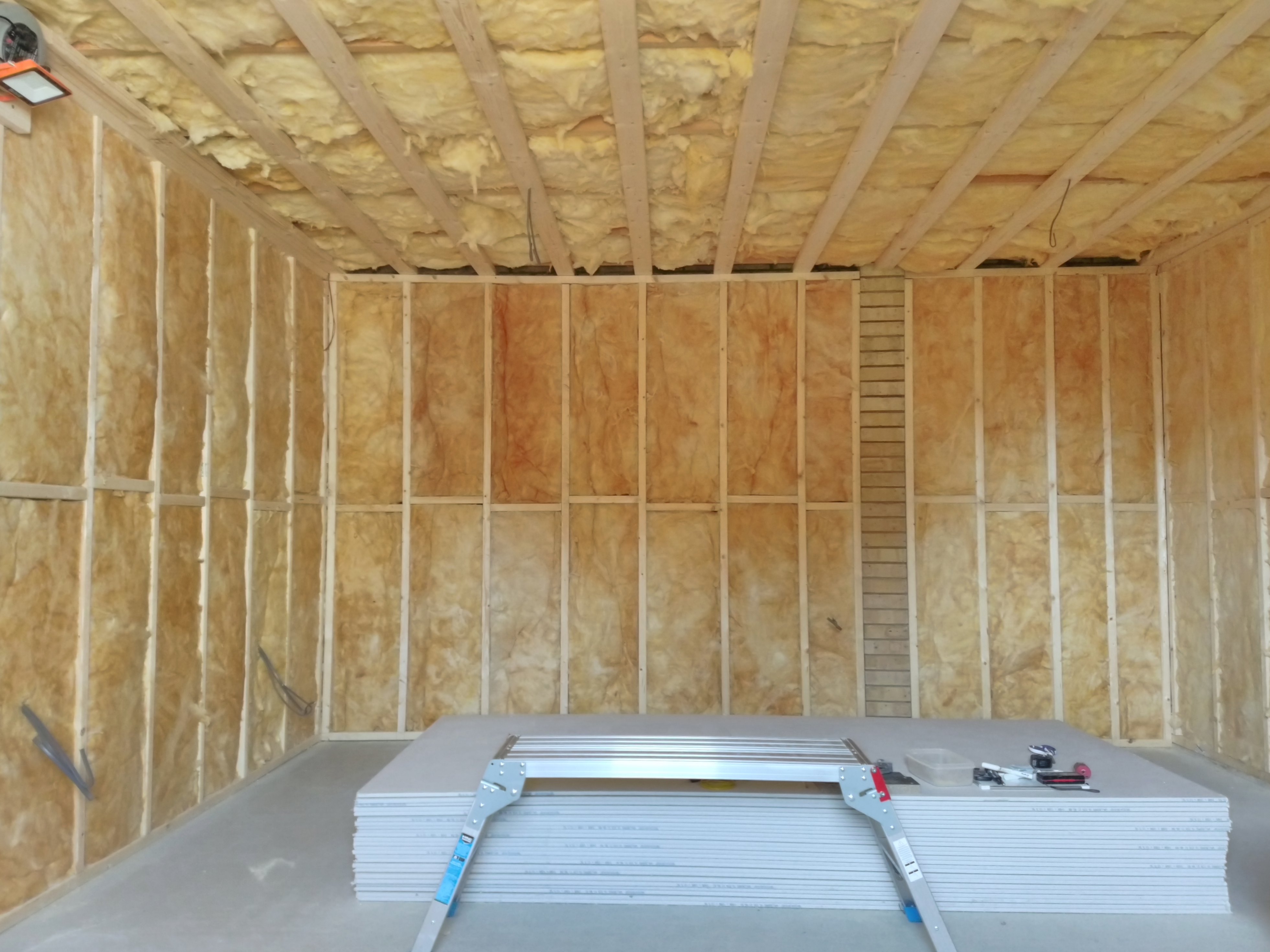
We ended up with a big pile of offcuts and a number of spare slabs. Some of that went up on the ceiling during the flooring build up there, but we bagged up most of the small offcuts and took them to the recycling centre.
After finishing the insulation, we covered it all up with a vapour barrier, preventing moisture problems. To be totally honest I’m still not 100% sure how this works, exactly.
We stapled this green sheeting onto the wooden framework, and then taped the joints together, making it as airtight as possible. Around cables we left the sheet a bit of leeway to fit behind electrical back boxes, and then used tape to seal the cable coming through to the sheet. I expect that many of these joints got some holes in them though.

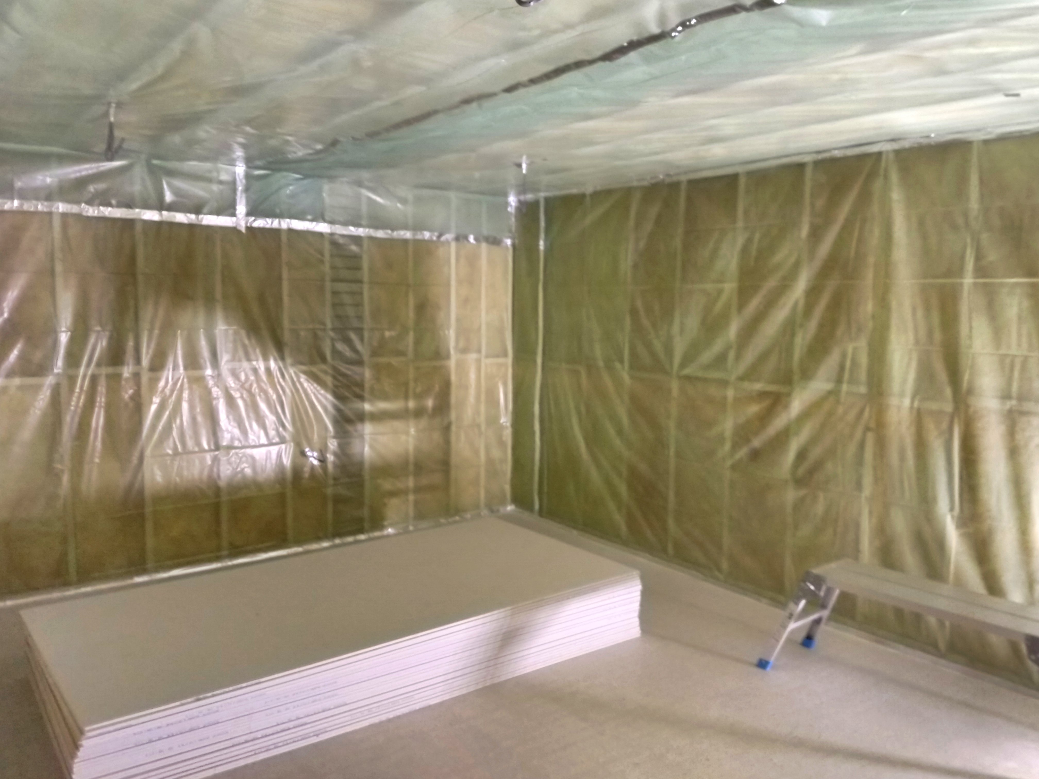
The room was then very quiet to be in; any sound got immediately absorbed into the walls. That was about to change, though…
Plasterboard Installation
Before starting off the plasterboard installation, I made sure to mark the location of all the wooden beams in the framework on the floor. With a board in front of it, it’d be impractical to find out where the beam is, making aligning screws tricky. With the help of the laser level I marked the locations of the ceiling beams as well.
The right angle marks on this nearest line indicate where two boards will meet.

While discussing our plans on a Discord server a while back, someone enthusiastically recommended hiring a board lift to vastly simplify the task of fixing the plaster boards to the ceiling. The alternative way would involve some home-made t-shaped props to keep them in place, but in comparison, it sounded like a complete pain. I’ll repeat the recommendation; if you’re going to plasterboard a ceiling, hire a board lift (also known as panel lift, drywall lift), and you can even do it on your own.
This video is a good demonstration: “How To Install Ceiling Drywall Using A Panel Lift” by Home RenoVision DIY
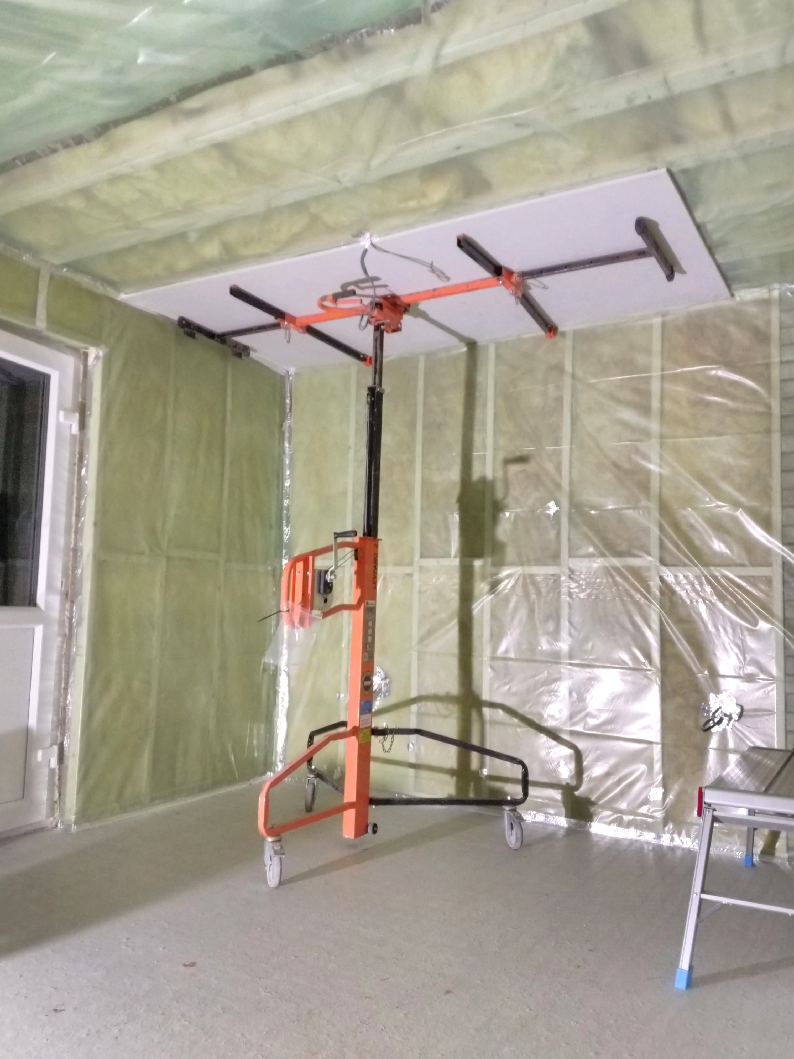
The top portion of this board lift can be tilted to almost vertical, allowing setting down a board on it with relative ease. A latch is then undone to tilt it to the horizontal position, which locks in place. A lever in the middle pulls a steel cable, extending the telescopic arm. It uses a ratcheting mechanism, keeping it locked in position unless you turn the lever the other way.
The lift can be wheeled around to position the loaded board exactly where needed. Wheel it into place, and raise the platform to press the board up against the joists. If it’s not quite positioned right yet, lower the pressure a bit and shove it around until you’re happy. Then, tighten it up again, and leave it there while you screw the board into its permanent position.
I installed plasterboard screws in 4 lines per full board, and then spaced the screws roughly 15 centimetres apart on each of those lines. I used an impact driver and a special screwdriver bit that prevents sinking the screw in too deep.
Scribing Plasterboard
We had to cut some boards down to size, using a method called “scribing”. I sadly have no photos of this process but I’ll describe it.
- Draw a line on the front of the plasterboard where you want the cut to be. Make sure all cuts go all the way across the length or width of the board you’ve already got
- Make a cut with a box cutter along a ruler lined up with your line. It mainly has to be through the paper layer of the plasterboard, but you can go through a few times to get deeper into the plasterboard itself
- Carefully flip over the board, trying not to put any strain where you’ve just made a cut
- Lift the board evenly beyond the cut line, causing the plasterboard to snap along that line
- Lift it further to form a small angle, then cut along the back of the line with the box cutter. Do this gently so the paper at the back doesn’t crunch up. The start and end might be trickiest here. Try to prevent ripping the paper.
For the walls, we had to trim a bit off the bottom of each board, as our wall isn’t quite 2.4 metres tall. We left a gap of a few centimetres on the bottom which would later be helpful for doing the floor. To install wall boards, the process was:
- Cut a bit off the bottom of a board
- Move it into position, laying it flat on the floor in front of it
- Set up the laser level’s vertical beam to indicate where one of the beams behind the plasterboard is
- Place the impact driver and bucket of screws within arm’s reach
- Stick foot into a board lifter (the metal thing on the floor)
- Lift board from the end away from the wall to be vertical
- Lift the board onto the foot-mounted board lifter, move it into position, and use foot in board lifter to press it up against the ceiling board
- Hold it there with foot and maybe a hand or knee, while reaching for impact driver and screw
- Install about 12 screws on the edges of the board and on the line indicated by the laser level, so the board doesn’t require manual support anymore
- Remove board lift from underneath
- Install remaining screws, moving around freely
Steps 7-9 were definitely the most strenuous, being in an awkward position holding the board still while getting the initial fixing in place done.
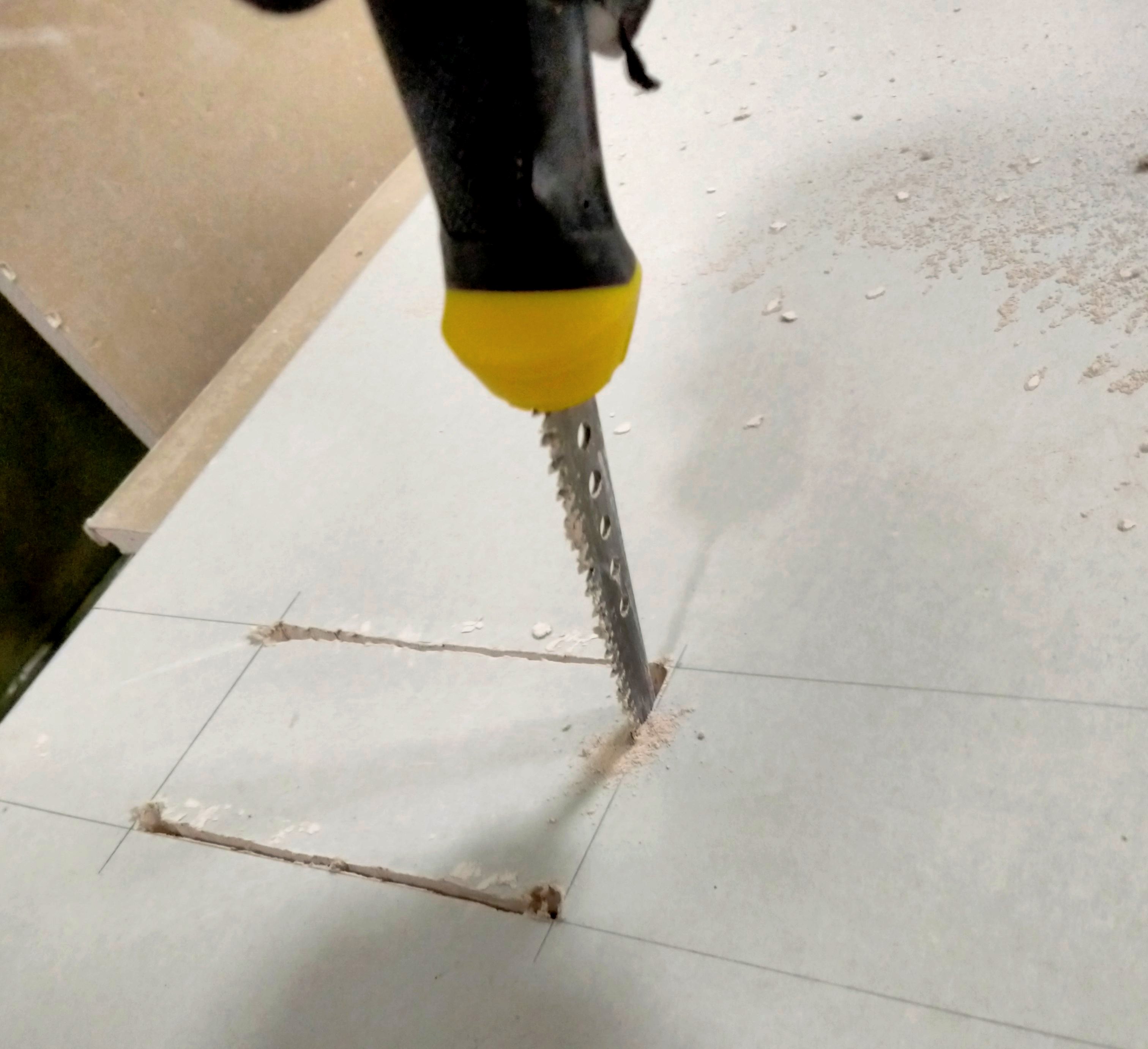
In boards that would contain sockets or light switches, I made a cutout. This required a drill and a special saw called a “jab-saw”. The process:
- Mark out the outline for the cut
- Carefully drill holes of about 5-7mm diameter on the inside of each corner of the outline
- Poke the jab-saw through one of the holes, and gently saw through the plasterboard inside each of the outline’s edges until you get the piece out
- Test fit the back box; if it’s too tight, use the jab-saw to scrape a bit off the tight edge.
The Electrical Installation That Was Too Soon
Once I had the plasterboard up, I got a bit too eager. Right after I finished the ceiling, I installed the main lighting, connecting a main plug to the cable that would end up connecting to the light switch. While I’d have to take this down again, it did provide much nicer lighting to work in in the meantime, compared to a single work light sitting on the floor.
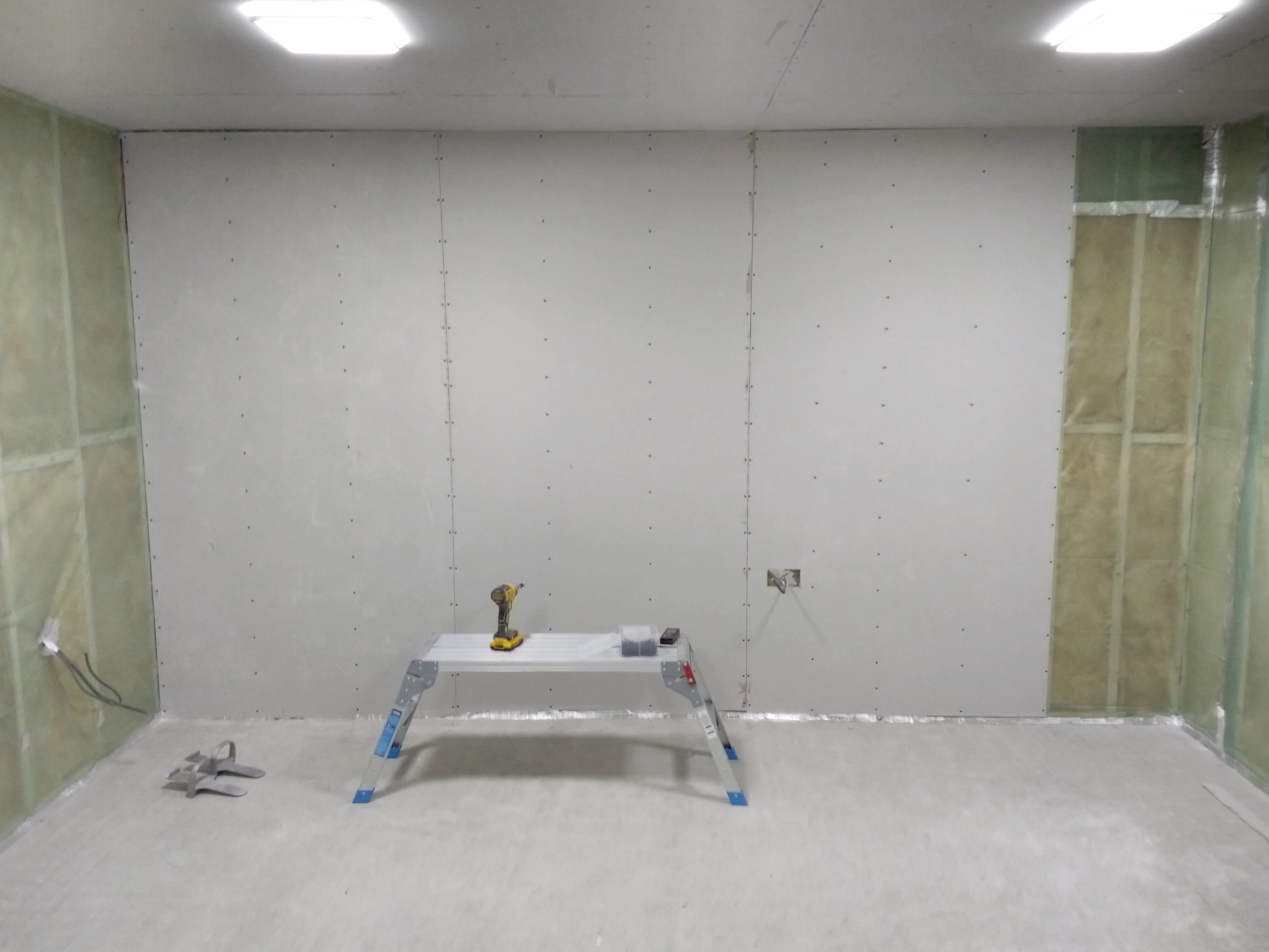
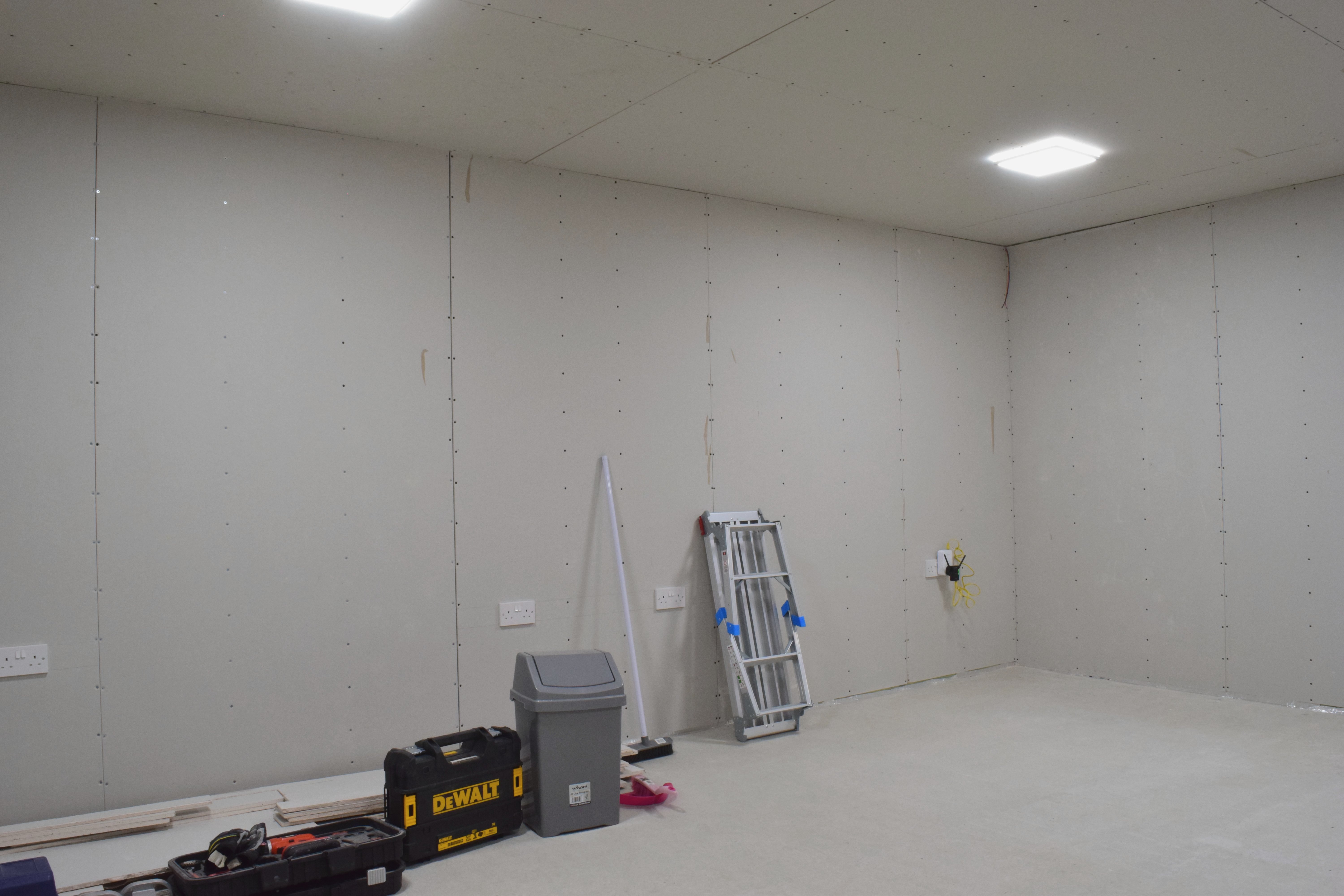
Once the walls were covered, I installed the sockets and switches as well, and finally wired it all up to the relevant junction boxes on the other side of the dividing wall. I even tested our “powerline” network connection over the new sockets; everything worked perfectly. I was pretty pleased with how much more finished the room now looked, but given the next step of skimming the plasterboard / plastering, I had to remove all the sockets and lighting again.
Anyway, here are a couple photos of what the room looked like at this point. These ones were taken with a pretty decent camera, for once.
Plastering
By the end of November 2021, we gathered the tools and materials to begin the plastering process, marking the start of the messy stage of the project.
One mistake we made is buying plasterboard with square edges. Had we purchased plasterboard with tapered edges, we could’ve covered the joints with scrim tape and filled them with joint compound to create an even surface, which would’ve saved a lot time. Instead, we had to coat the entire wall in a couple of millimetres of finishing plaster.
Anyway, it was a good learning opportunity.
To prepare, we covered all the joints with scrim tape, a light “grid” tape that provides the plaster with more to adhere to, making it much easier to adequately cover the gap where boards meet.
I disconnected all the sockets, the switches, and their back boxes. I then tied sandwich bags around the wires so they wouldn’t get covered in plaster and paint.
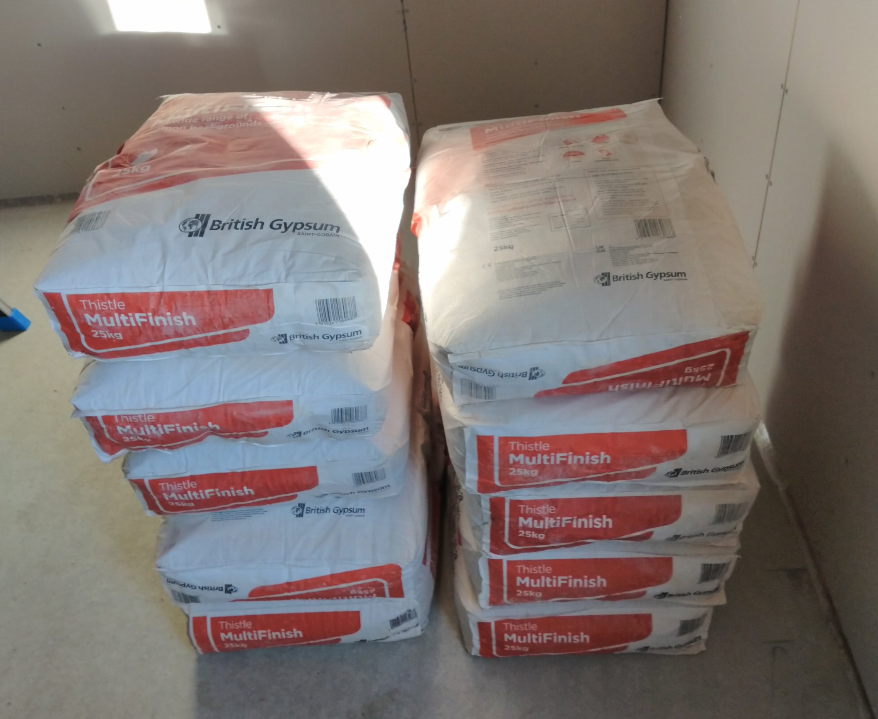
These bags of finishing plaster were 25 kg each; fun to carry in.
After watching several YouTube videos, we went to work.
We mixed part of a bag of plaster with water in a big mixing bucket, using a mixer power tool. We brandished our “hawk”, a large metal square with a handle mounted in the middle of it on one side, on which you carry around a bunch of plaster. We loaded up some plaster from the bucket with a trowel (like a scoop), and set to work spreading it out on our respective ends of the wall, with a tool that’s somehow also “trowel” but is very differently shaped to the first one. Because, you know, English.
This second type of trowel is similar to a hawk, but rectangular in shape, flat, and the handle is built parallel to the surface instead of perpendicular. It’s used to spread out and even out the plaster on the wall.
Rambling about tools aside, it turns out it is hard to get plaster nice and even, and do it before it dries out too much. We gave it a good go. We mostly made a mess of things in the corners, but otherwise did okay, in our amateur opinion.
We got a tool called a “SpeedSkim”, which is a semi-flexible bit of plastic (the “blade”) mounted to an aluminium handle. It’s about a metre long, and allows evening out large areas at a time, with much more ease than a trowel in an untrained hand. Using this, patience, and a spray bottle, we were able to get a smooth-ish finish on the walls.

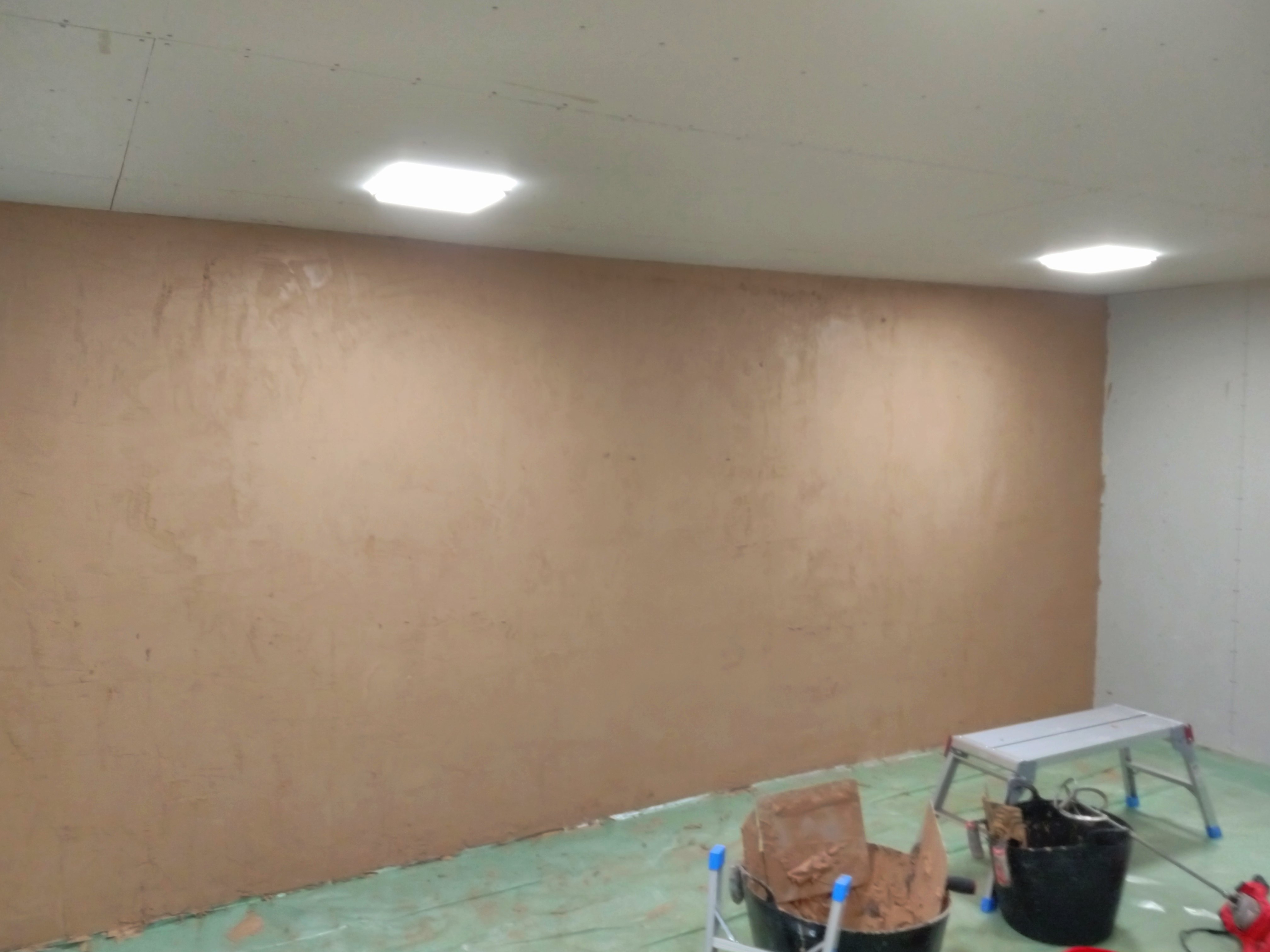
This is what our first wall looked like while the plaster was still quite wet, after using the SpeedSkim on it.
In our exhaustion after getting the first wall done, we didn’t bother cleaning our tools straight away. This meant that the leftover plaster hardened on it, making it all the harder to clean ahead of the next session a few days later. We had to use a wire brush to clean them off, but the trowels got a bit rusty.
For later walls, we started using a table to dump some plaster on. This setup made it easier to scoop it up with hawk and trowel. We (ab)used our coffee table with some left-over vapour barrier as a table cloth.
Around the door, we installed some corner bead, a metal bracket that reinforces external corners. These are fixed onto the plasterboard (and lumber behind it), with screws, and are then plastered over.
After finishing the last wall, we took on the ceiling. I took down the night light fixtures and bagged up the wiring. We invested in a dual work light on a stand; still a big improvement over a single light right on the floor.
The ceiling was very difficult to plaster due to our lack of experience and the awkward working position. Working upward with a weighty tool is no joke. We ended up with pretty uneven coverage, and quite ugly finish near the corners. I have to admit I did a much poorer job than Brittany did; my side of the room had many areas where the plaster was entirely too thin.
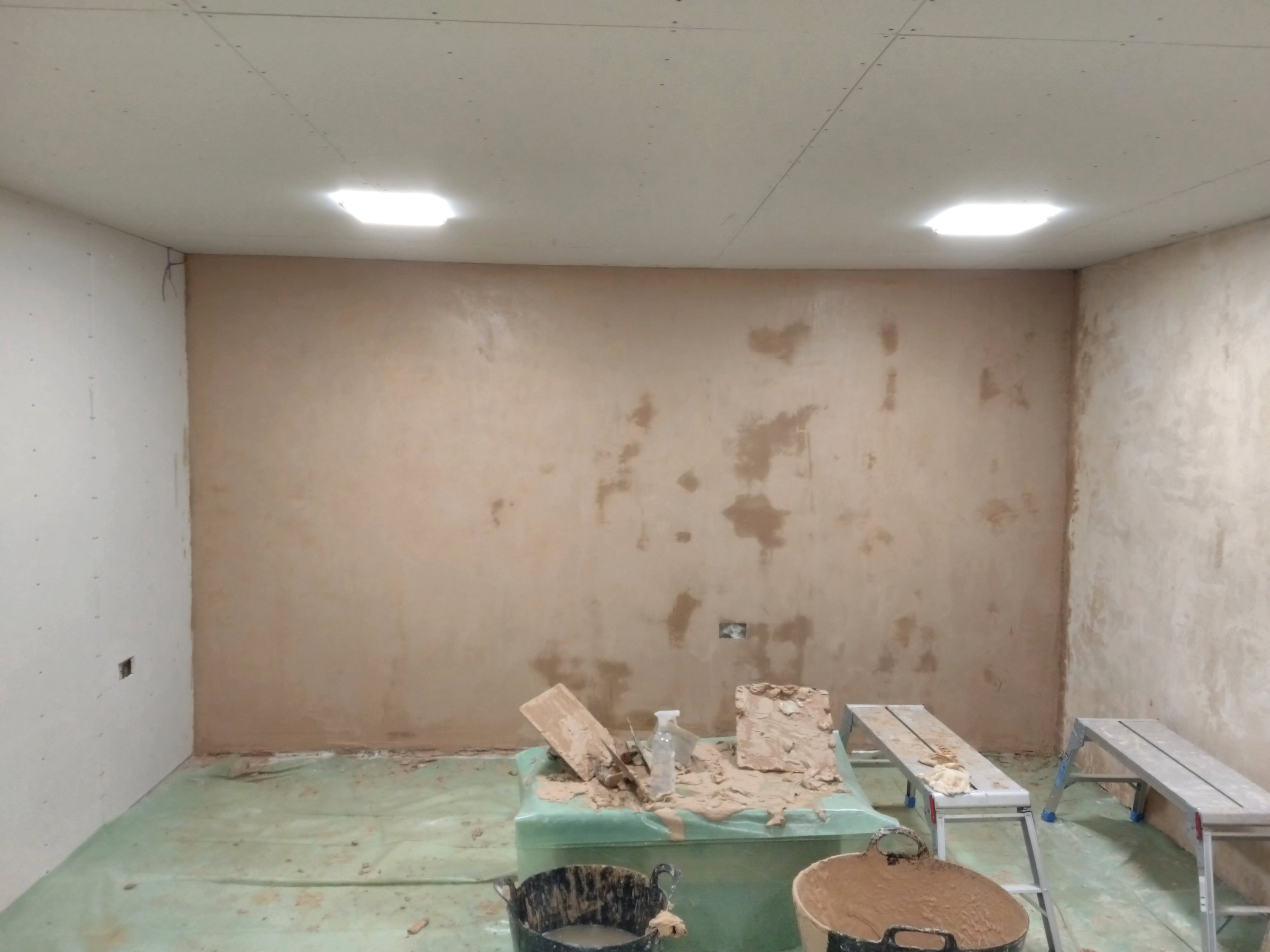
I think this picture was taken a day after we plastered the ceiling.
After our poor performance with the ceiling, it was almost Christmas. We visited family for the holidays, and by the end of it fell ill with a pretty bad cold. The lateral flow tests didn’t indicate COVID-19, but symptom-wise it probably was.
By the end of January, Brittany had done some research as to what to do about our ceiling, and found out about a plastering product by Knauf, “ProRoll Max”, which can be rolled on with paint rollers. We decided to go ahead with this product, and to our delight, it came out with a much, much neater finish. Brittany first prepared the ceiling with PVA (same kinda thing we used for the screed floor). We then rolled the plaster on with paint rollers, and used the SpeedSkim (on a pole) to even it out. We ended up doing covering the ceiling in two stages spread over two days.
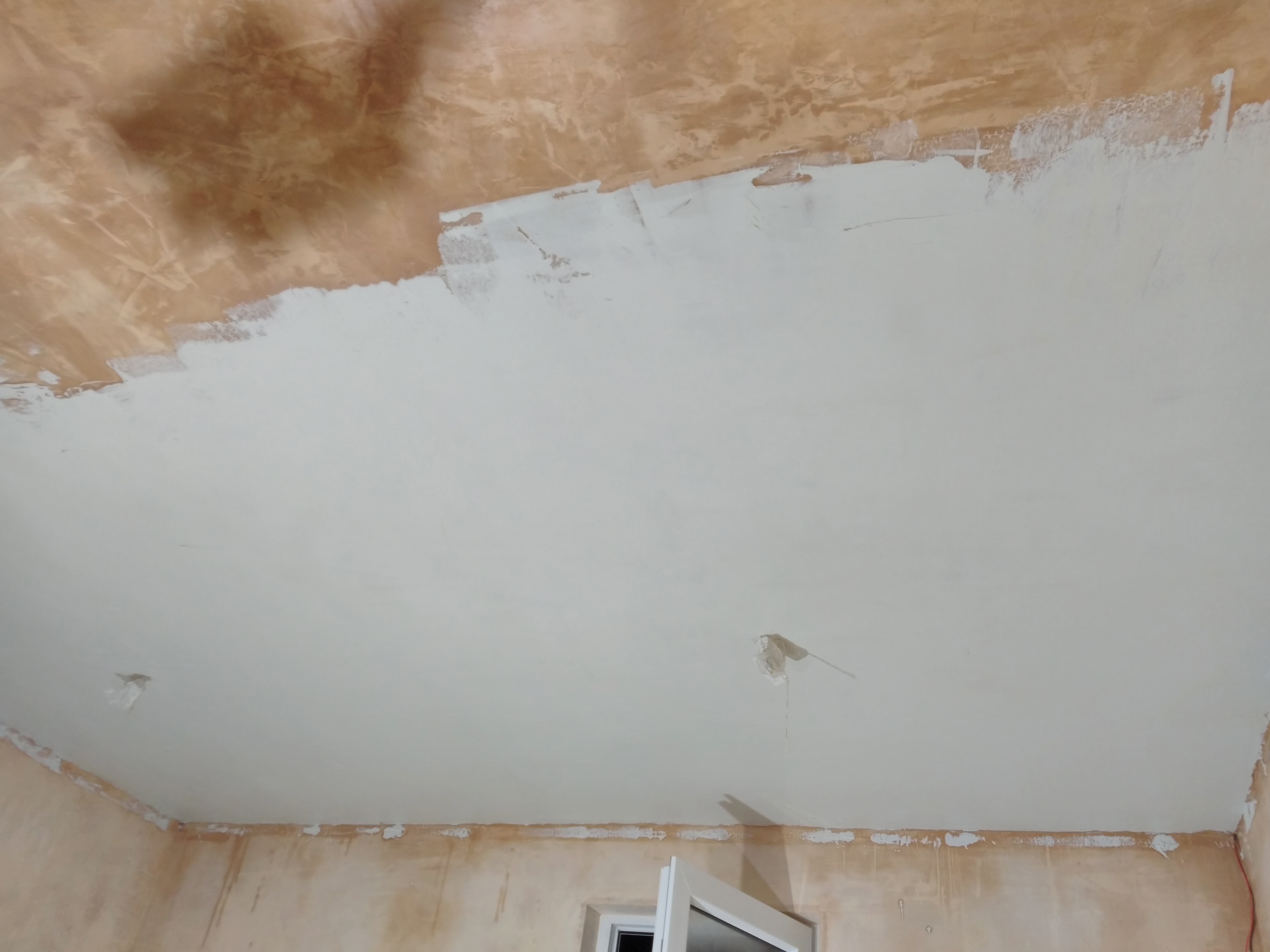
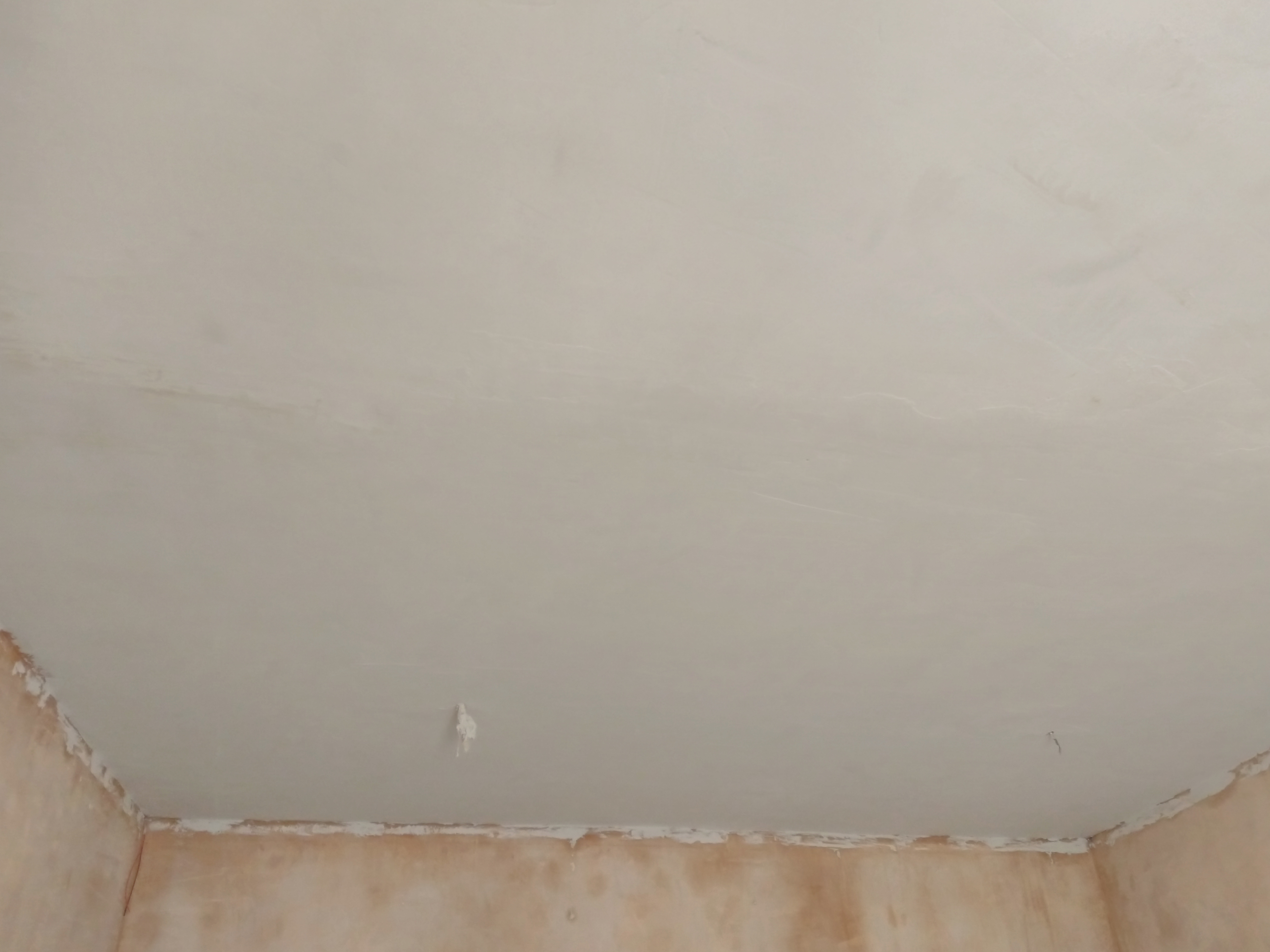
There certainly were some rough spots left, but we ended up with a very even looking ceiling, unlike the classic British Artex ceilings that we have indoors.
The next few days, I spent time with a chisel and a sanding block, cleaning off little bits of spilled plaster, and generally smoothing out the plaster before we moved on to painting.
Painting
At first, we decided to paint the walls and ceiling a pure white, maximising efficiency of the lighting. Later, we decided to add another coat of an off-white shade called “Timeless” to the walls to add a tiny bit of contrast with the ceiling.
Before painting, we installed coving; a very common decorative finish to hide imperfections in the transition between wall and ceiling– much needed in our case.
For the secondary lighting, there were wires dangling from each corner. We needed a way to route those to below the coving. My first thought was to make a little cut at the corner of each coving piece, and route the wires through there. This proved difficult, particularly to make the corner fit right. We ended up grinding a small channel in the plaster coat to allow them through, at a small offset from the corner.
The coving is made of a very light material, and is held up by a purpose-made glue it shipped with.
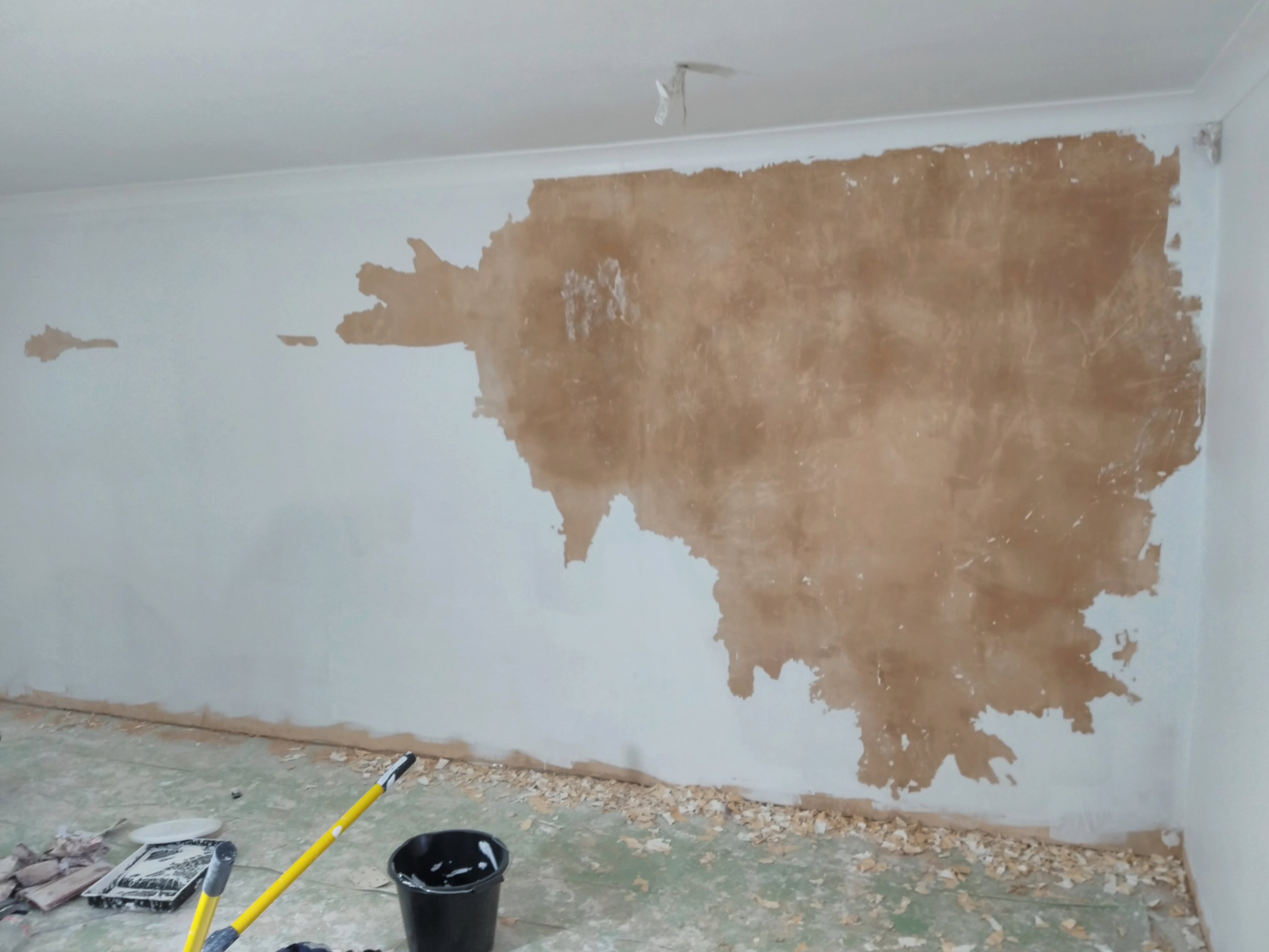
We put down a mist coat–regular wall paint thinned a bit with water–to start off. This coat acts as a primer, helping the normal paint stick to the plaster. We quickly noticed a problem: In several spots, the mist coat didn’t seem to be sticking to the wall. It left splatter-shaped unpainted areas. It turns out that while preparing the ceiling for the roll-on plaster, the PVA splashed around a bit, and we didn’t think to clean it up at the time. I guess we learned the hard way that PVA spills should be cleaned up if you’re going to paint the surface.
A couple of days later, we added a second coat of paint, hoping to finish it off. We quickly found that the PVA stains were still an issue. We decided we’d let the paint dry and then sand those areas down to the plaster to remove the PVA.
This wasn’t the end of our paint troubles. We neglected to pay attention to the temperature and, being February, it was quite cold. After a few days, we found that paint just peeled off some of the walls, like it wasn’t sticking at all.
Probing for the extent of this problem, I ended up peeling a large area. Lesson learned: leave a heater on in the room to allow the paint to dry properly.
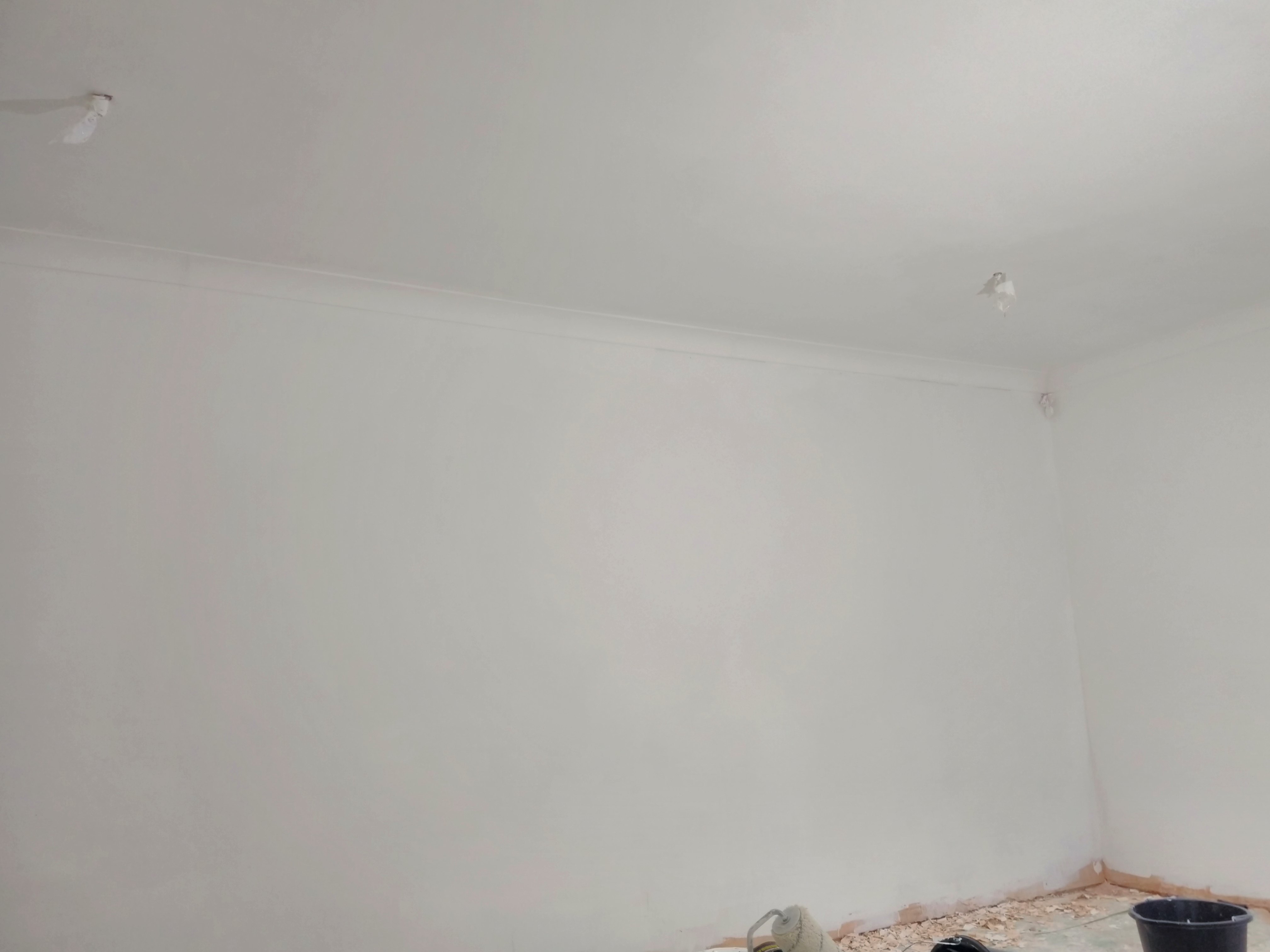
We repainted this wall in 2 or 3 layers, and properly heated the room that time; it came out looking nice.
Having finished the painting, I reinstalled all the sockets and lighting.
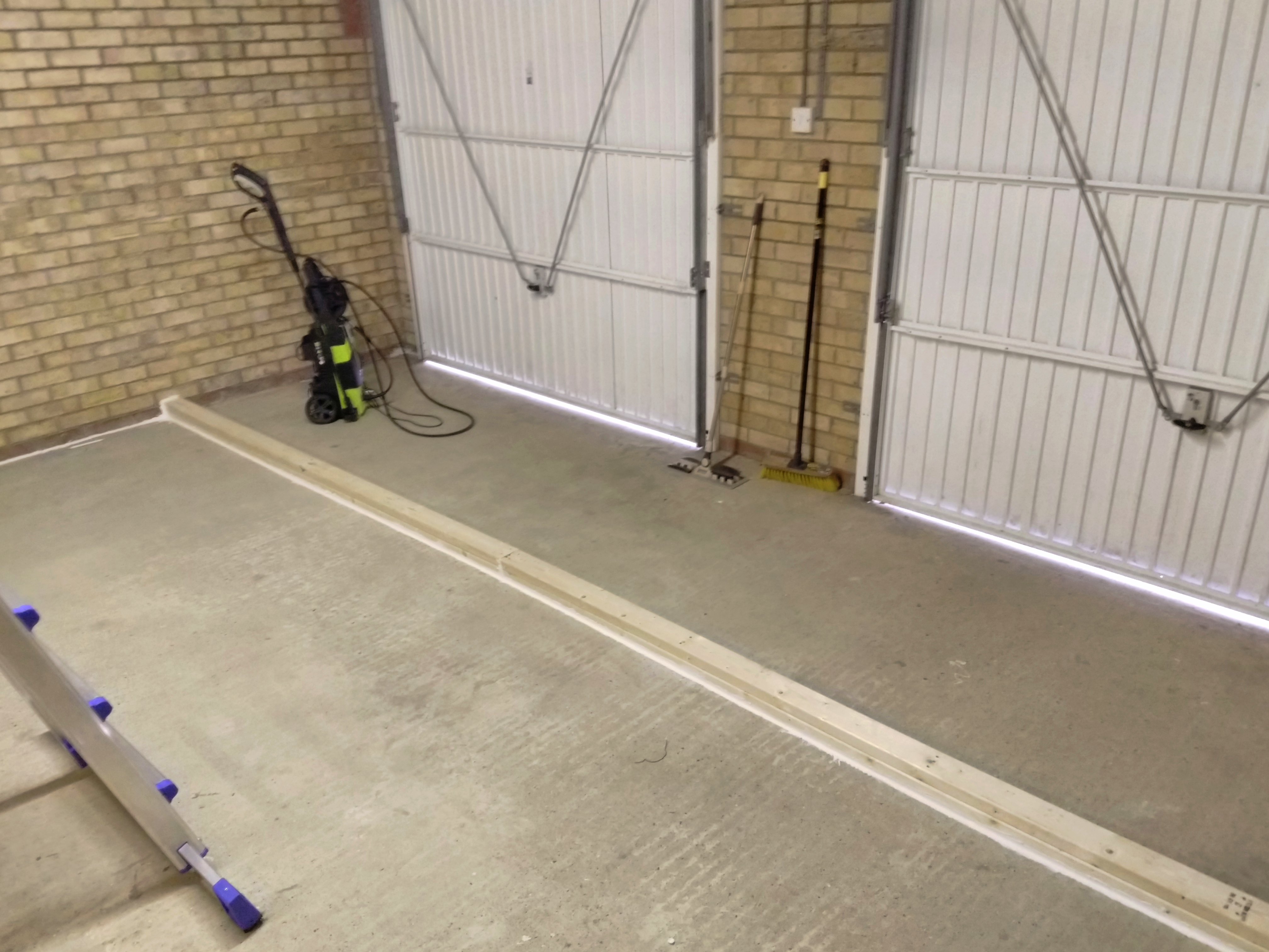
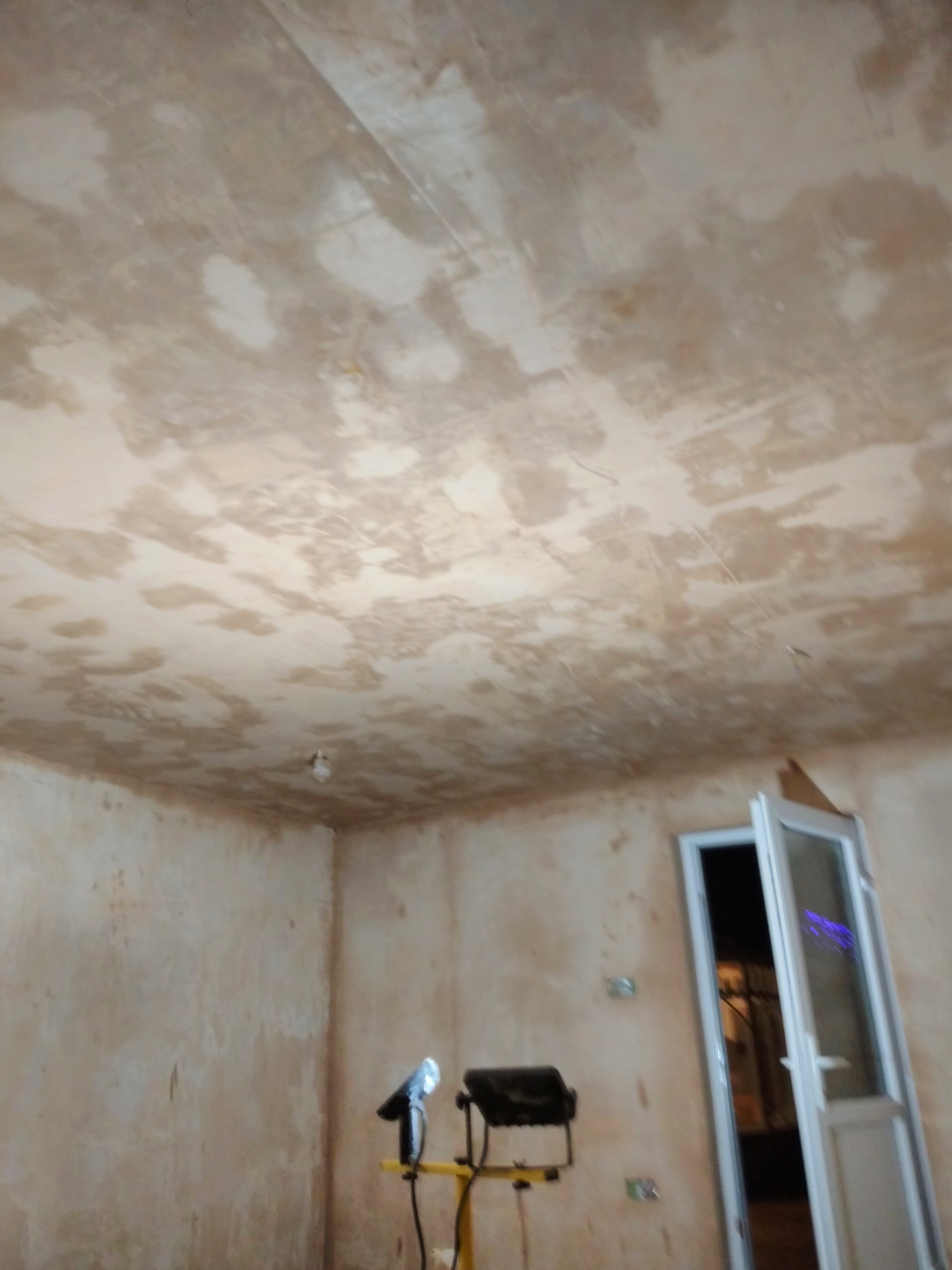
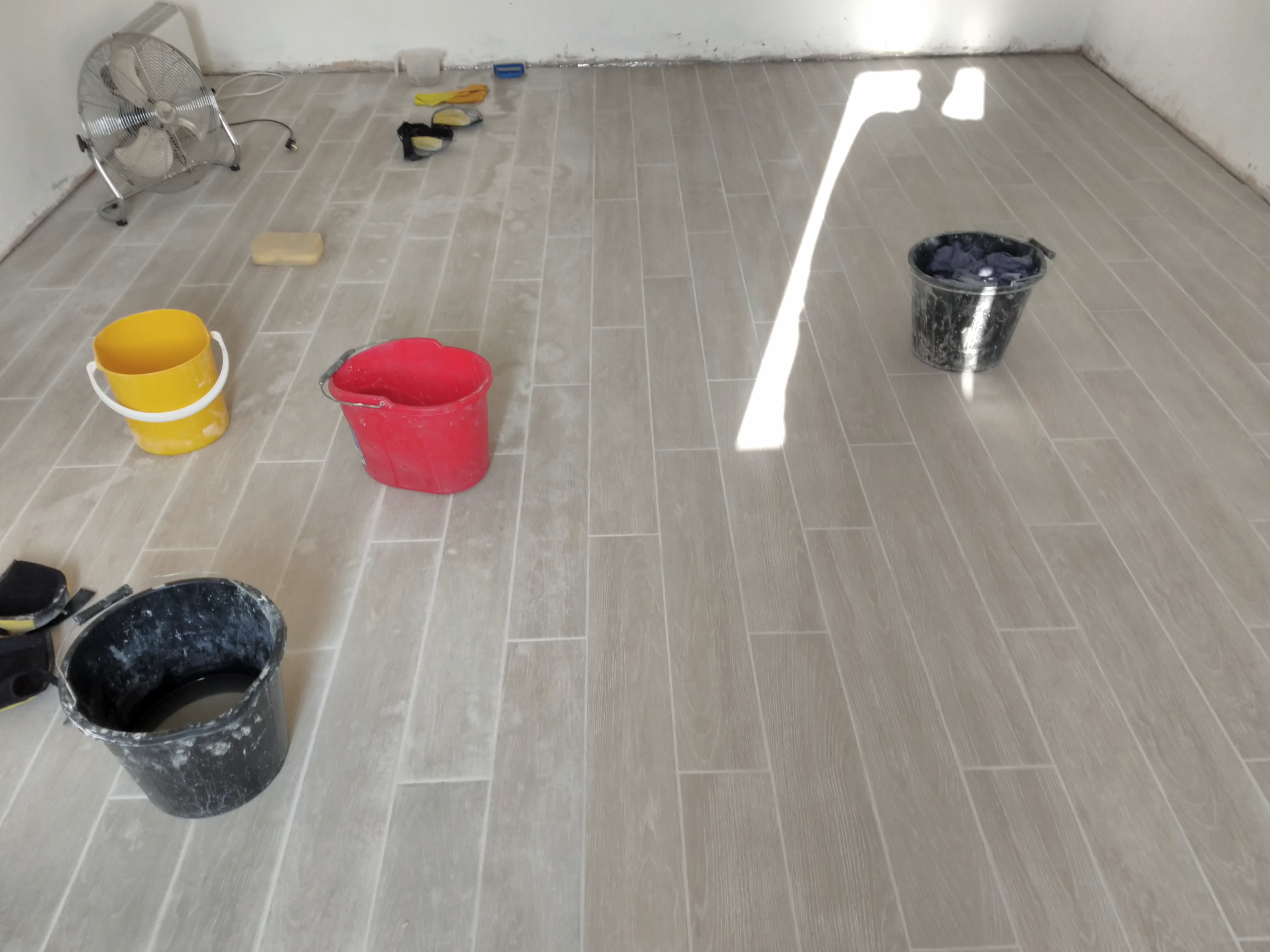
Plastering and painting made the floor a right mess. The next job was to tile the floor, so I took great pleasure in cleaning it all up. Here’s a picture before that cleanup:
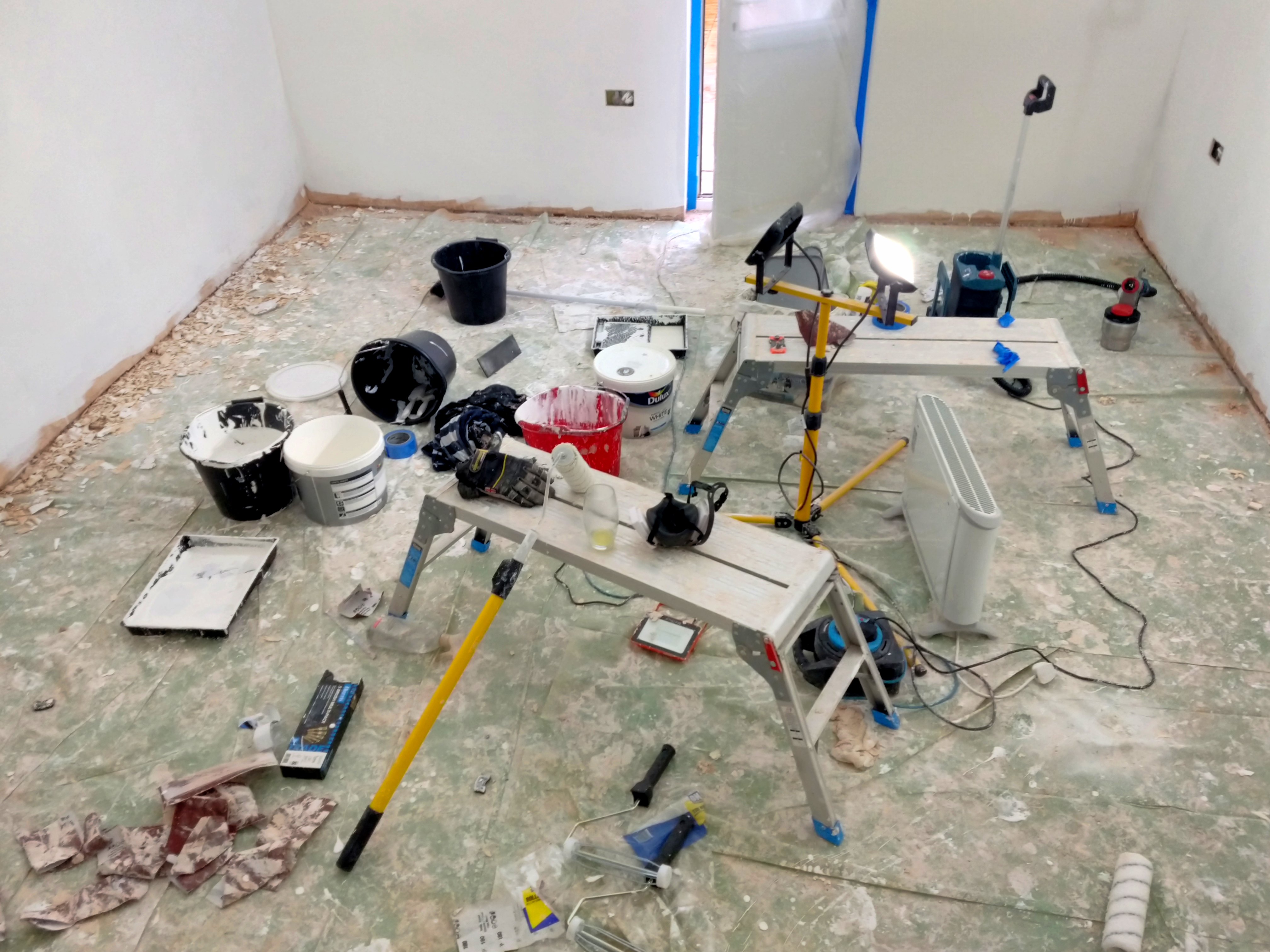
After that clear-out, only this remained (apologies for the somewhat blurry shot):

Tiling the Floor
Our goal for the floors included:
- Bright
- Hard
- Easy to clean
- Easy to find small items on (when working on electronics)
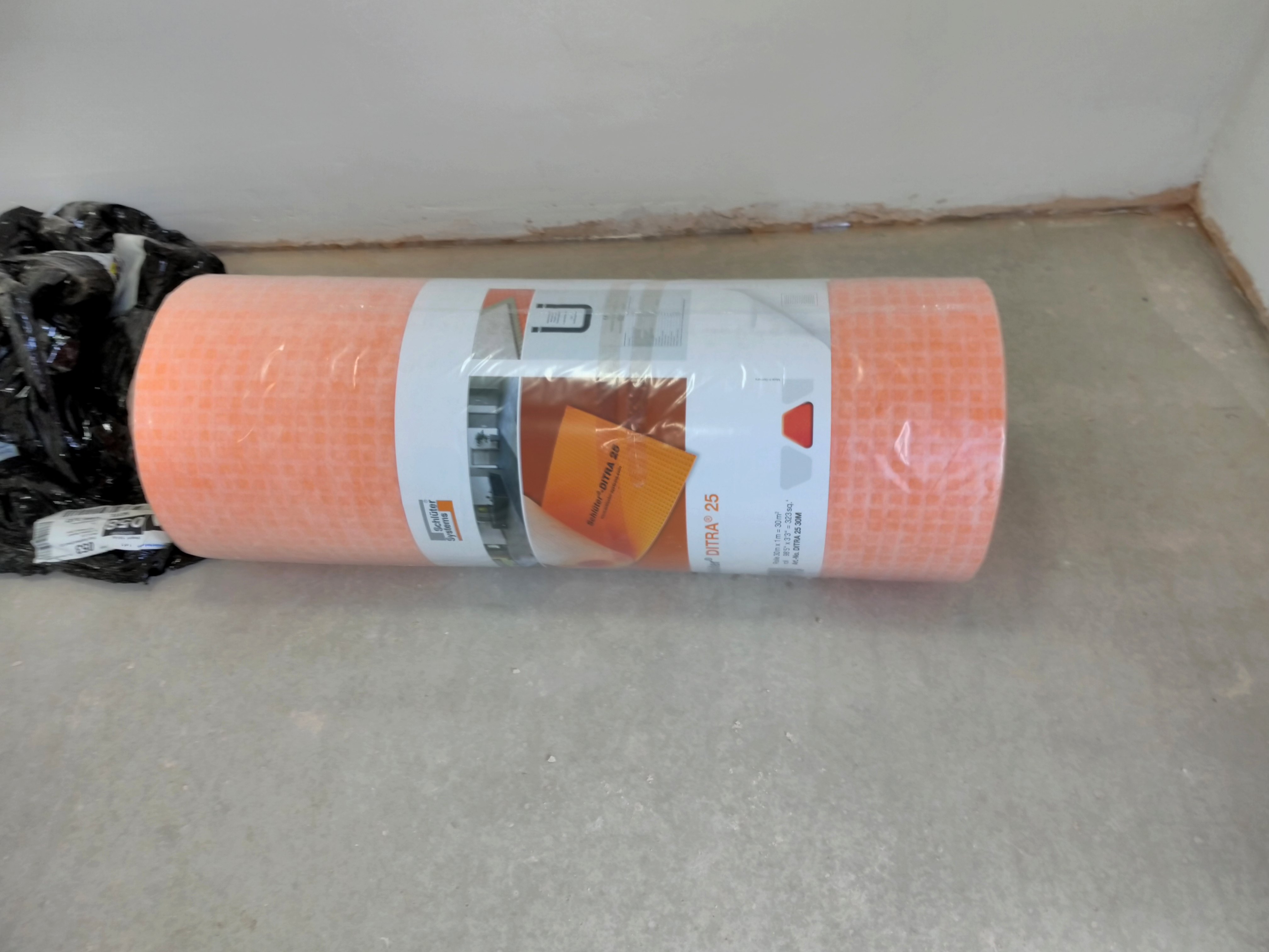
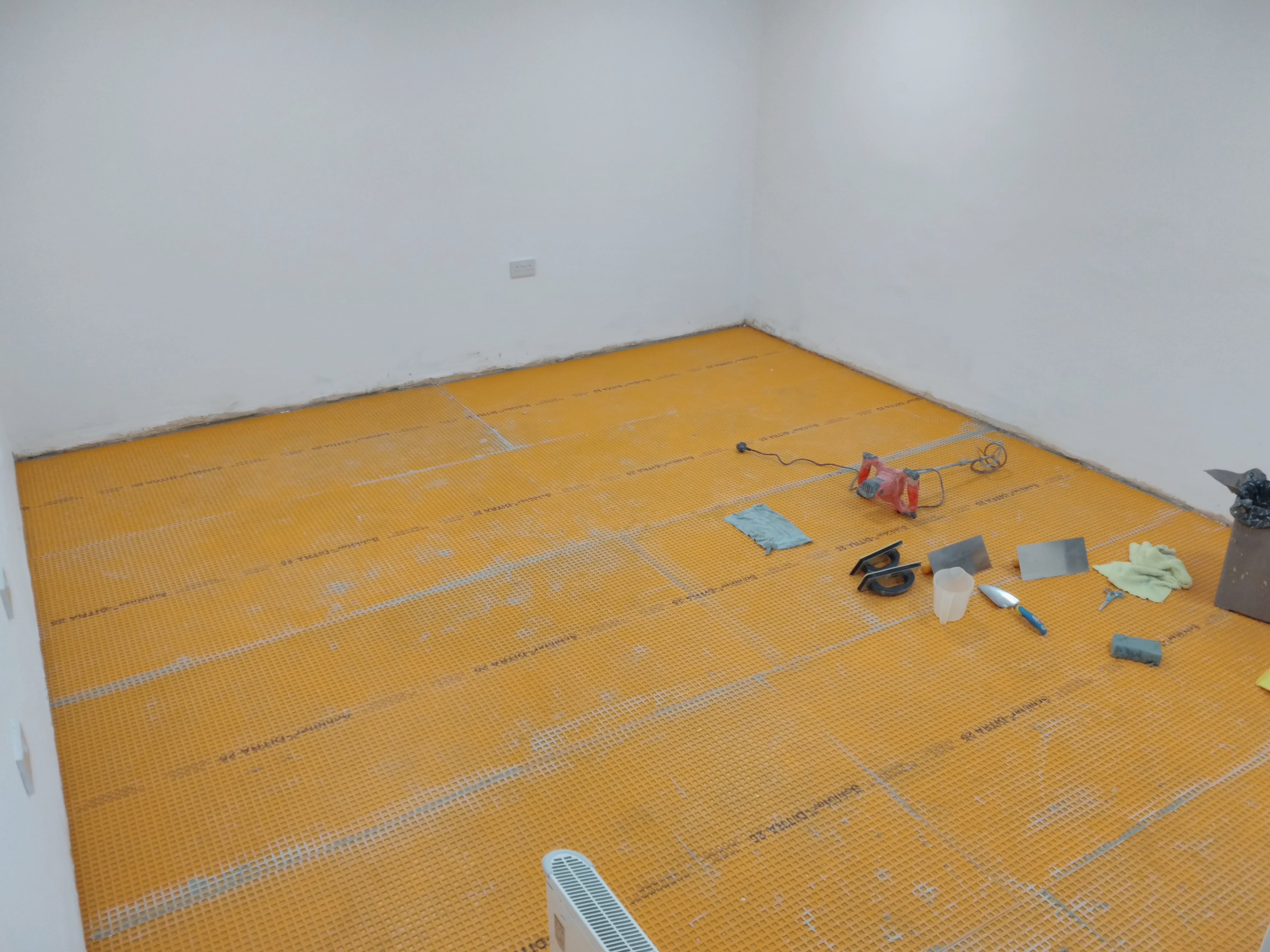
We picked a wood-effect porcelain tile, plank-shaped. Advice online indicated it’s best to have a decoupling layer between the floor base and the tiling. This layer prevents tiles or grout from cracking if the concrete underneath shifts and develops cracks. We had already noticed some very thin cracks in the cement floor, so this seemed like a pretty good idea.
We went for some very orange stuff called “DITRA” by Schlüter Systems.
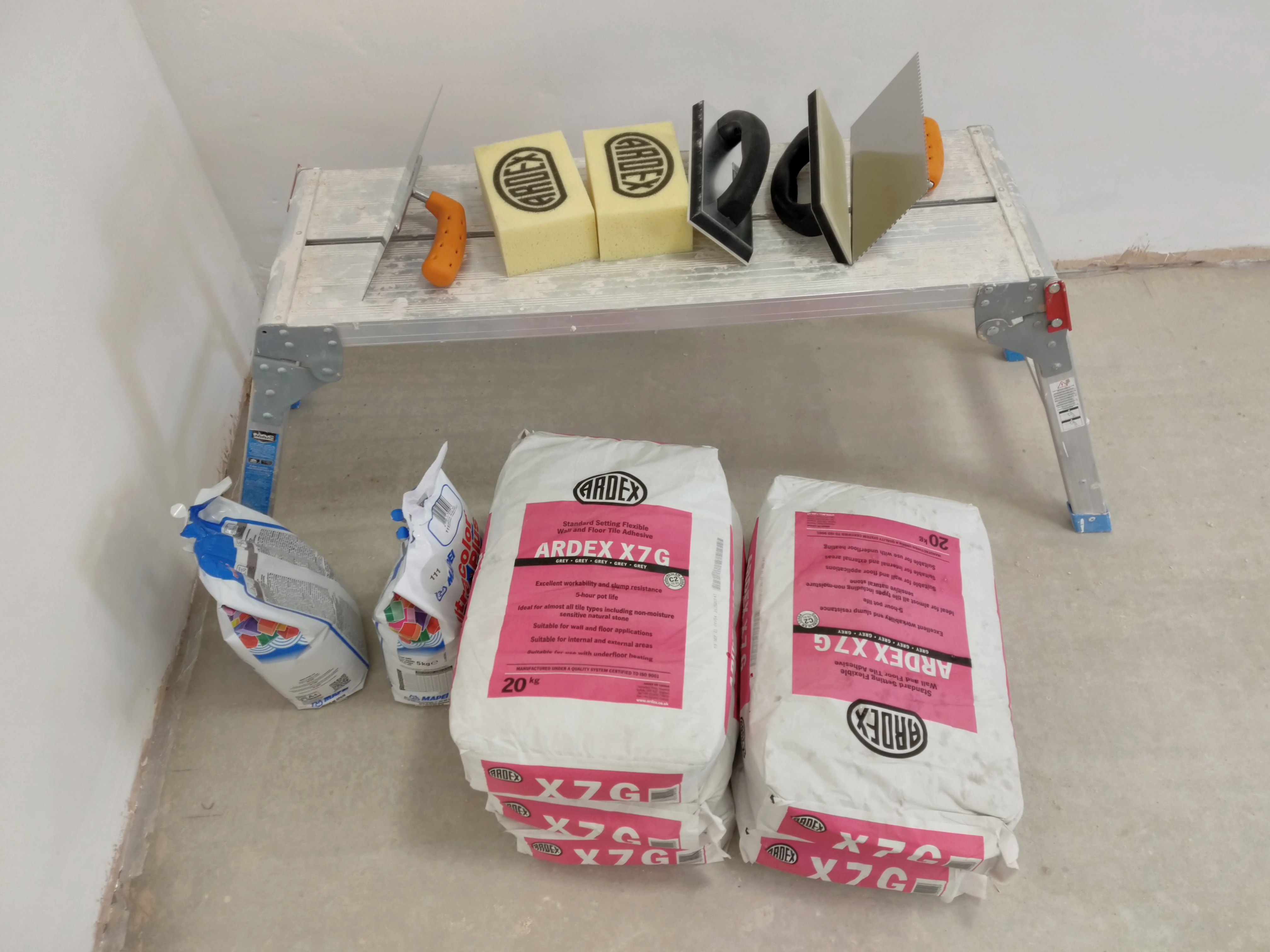
We ordered our materials: The floor de-coupler, mortar, grout, tiling trowels (with the square notches), floats, sponges, and of course tiles.
We also got some knee pads since we’d spend a significant amount of time working on our knees. These would have been useful earlier in the project too.

Decoupling from the Concrete
First, we installed the floor decoupling membrane. We cut lengths as wide as the room (the shorter length) from the roll, and then cut those roughly in half. We first did a test fit, so we cut all the pieces upfront.
We then applied a layer of mortar, and added more to drag lines into with the trowel. The important thing was to “not make swirls” as per several tutorial videos. I don’t suppose it mattered that it wasn’t otherwise fully uniform.
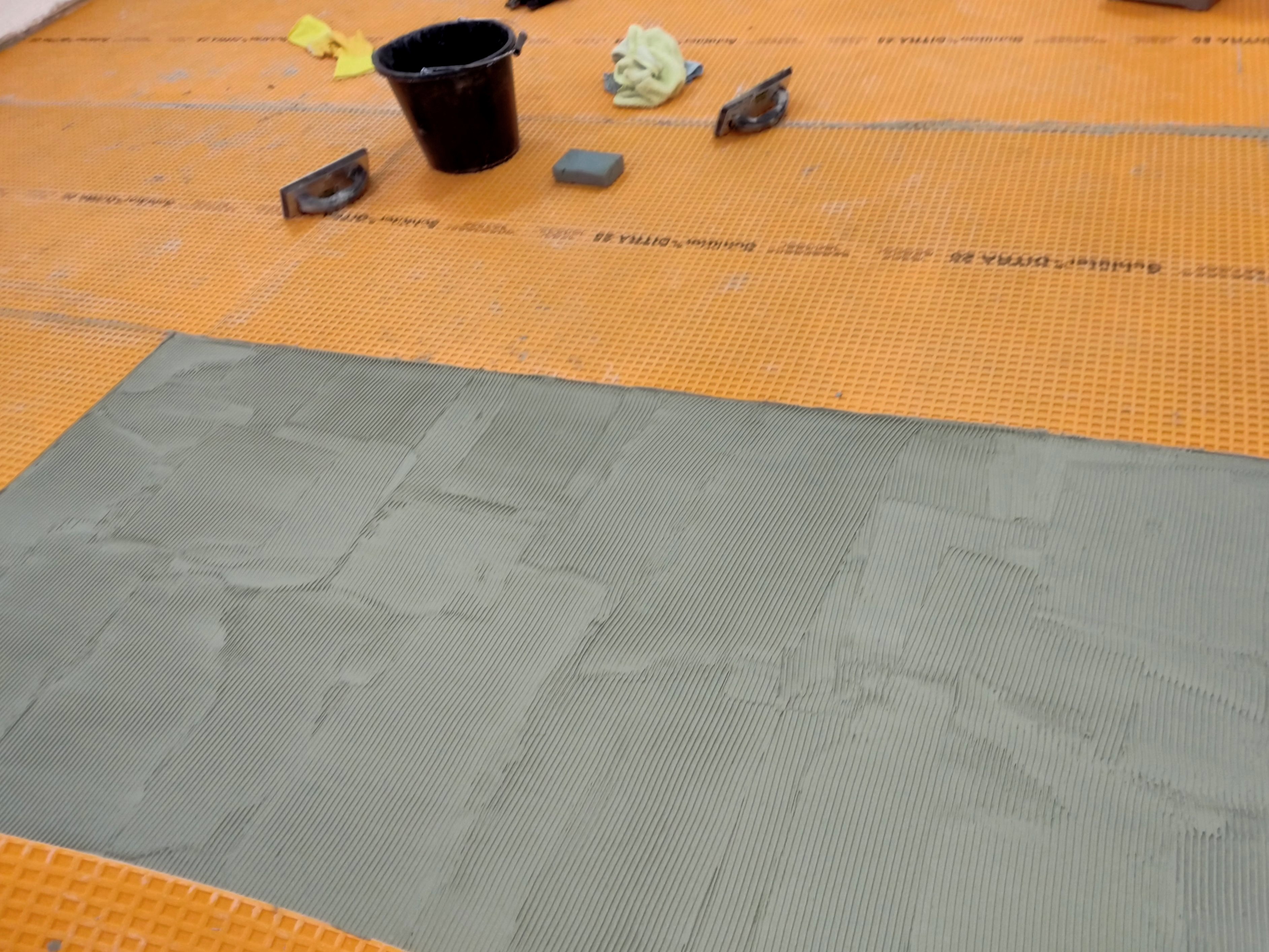
After applying mortar like this, we’d carefully lower a section of the DITRA onto it and pressed it down into the mortar with our floats. We made sure to not leave any (significant) bubbles of air underneath, and pushed out excess mortar to achieve as flat a finish as we could.
Tiling
After consulting several videos on starting the tiling process, we measured out the starting point: two tile widths away from the wall. We marked this line with a piece of skirting board, held down firmly with two left over bags of plaster mix. This was aligned with the help of the laser level, and multiple measurements.
We prepared a batch of mortar, and Brittany started out with the first few rows.
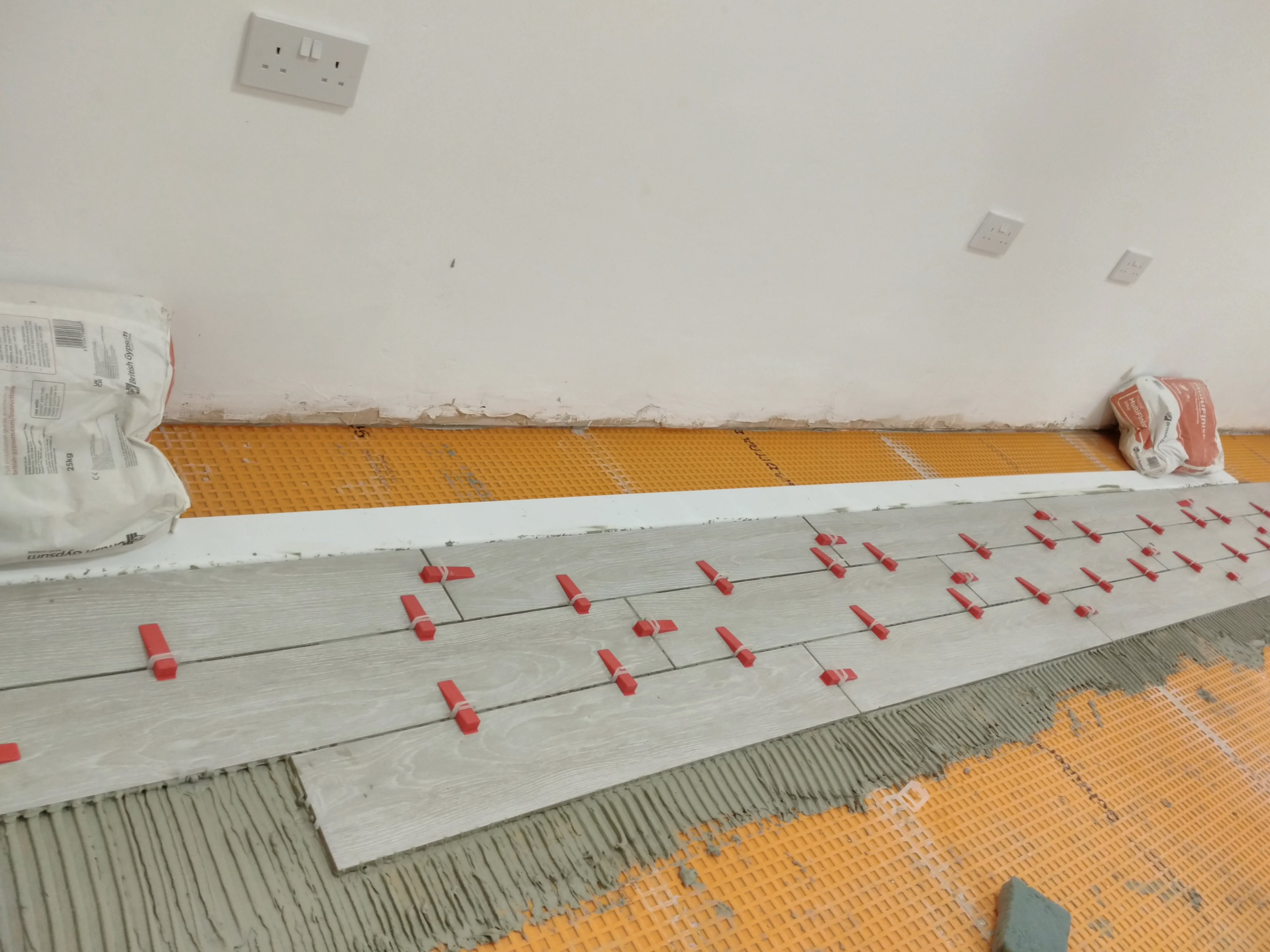
We used a self-levelling spacing system, made of spacers you stick underneath the tile’s edge and a wedge piece that forces two adjacent tiles to be on the same relative level. The system came with a specialised hand tool to squeeze wedges into the spacers. This system made it much easier for amateurs like us to achieve a nicely level finish.
I joined in later that evening. We removed the skirting board guide and added the two rows up to the wall that day, and cleaned up the excess mortar.
Sticking down a tile involved:
- Spreading mortar on the subfloor, forming ridges in a single direction
- (Optionally) cutting a tile to size with the wet saw (wearing ear, eye, and hand protection)
- Spreading a thin layer of mortar on the back of the tile, called “back-buttering”
- Placing it on the floor, on top of the self-levelling spacers
- Pressing it down into the mortar, jiggling it around for good coverage
- Firmly pressing it down as much as possible, squeezing excess mortar out from under the edges
- Cleaning up the excess mortar with gloved fingers and a moist sponge
- Inserting the wedge parts of the self-levelling spacers using the tool
This process continued over roughly a week of almost daily progress. After a while, we ran out of wedges, and had to remove them from earlier rows with the help of a mallet.
We purchased a pair of “grout rakes”, designed to remove grout, but here used to remove excess mortar between the tiles. We want grout to fill the gaps, not mortar.
One evening, we hoped to finish the job, but underestimated the work left. We tried to speed things along by skipping the excess mortar cleanup until the next day. I can feel some of you grimace as you read it. This made the cleanup much harder, so our recommendation is to do as everyone advises… clean up the excess mortar immediately.
We managed to clean up with water and a sacrificial mop (applied with a lot of force), but that lead to another problem: water seeping under tiles where the mortar hadn’t fully set yet. While raking the grout from between these tiles a few days later, I found that those few had a hollow sound to them when tapped. I quickly found they came loose entirely.
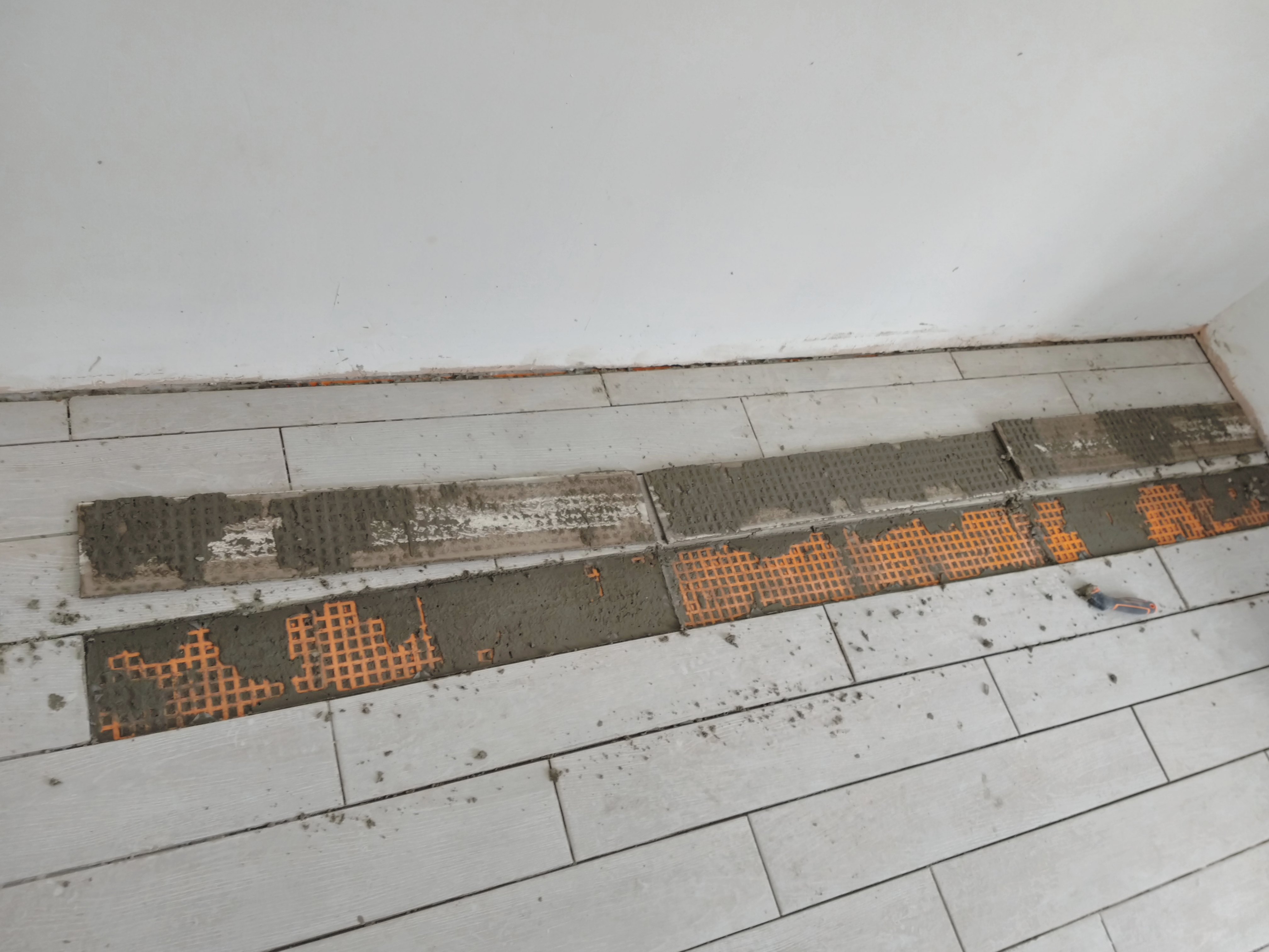
Brittany cleaned up the mortar on and under them, and reapplied fresh mortar to stick them down properly—a bunch of work we could’ve avoided.
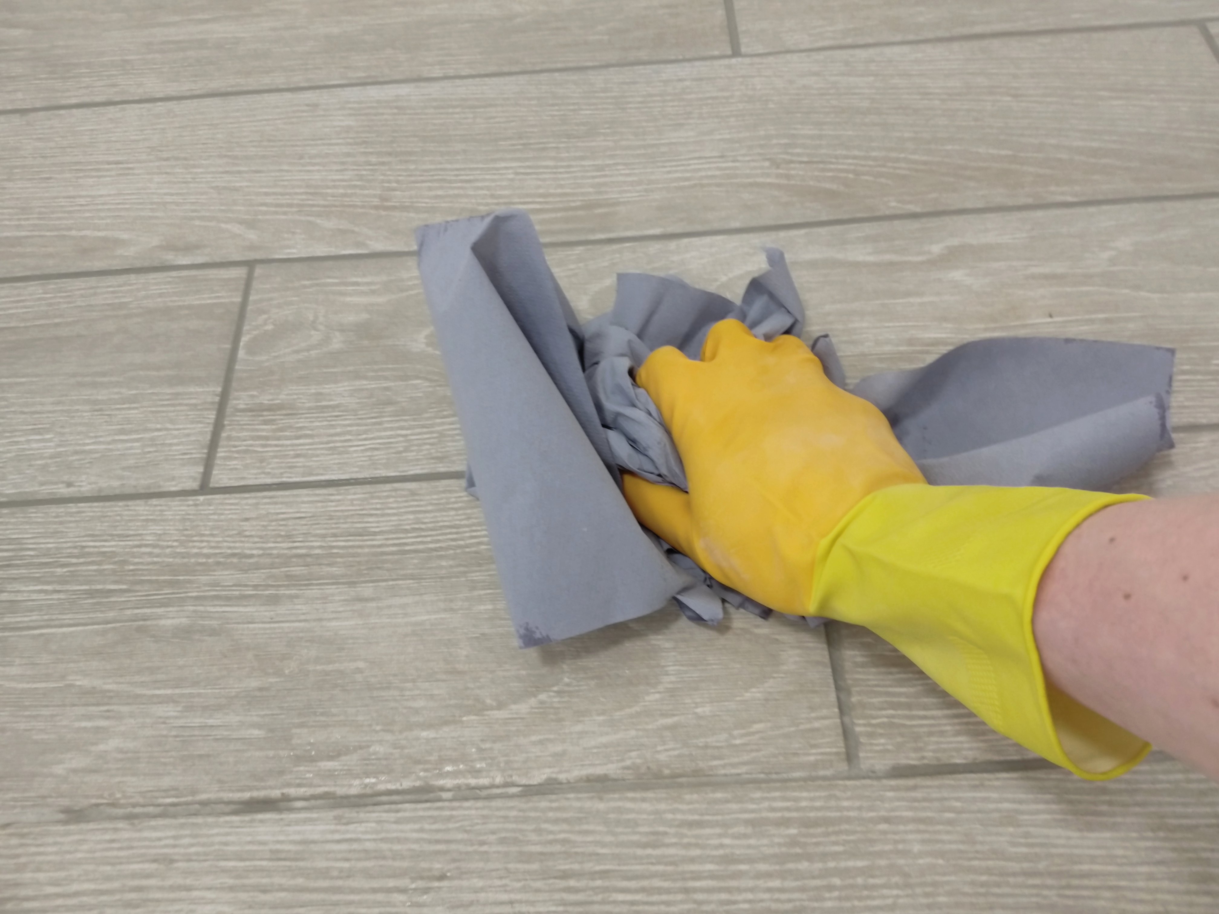
Cleaning Mortar Stains
At this point, the floor was in pretty good shape. When wet however, it clearly showed mortar residue stains all over the place. I first tried cleaning them with a sponge and water, as well as with some grout cleaner, but didn’t have much luck. Scrubbing the residue off was far too physically demanding. In frustration, I tried out a wire brush on an inconspicuous corner and found it did the trick beautifully. Porcelain is a very hard material, so this wire brush did not scratch it at all. It did get the residue off though. The brush didn’t damage the tile, but the tile really ground up the bristles. It left metal shavings which were very easily cleaned up with a sponge.
Cleaning the entire floor was still a large effort, but the progress was visible and predictable.; more than could be said of the chemical + sponge process.
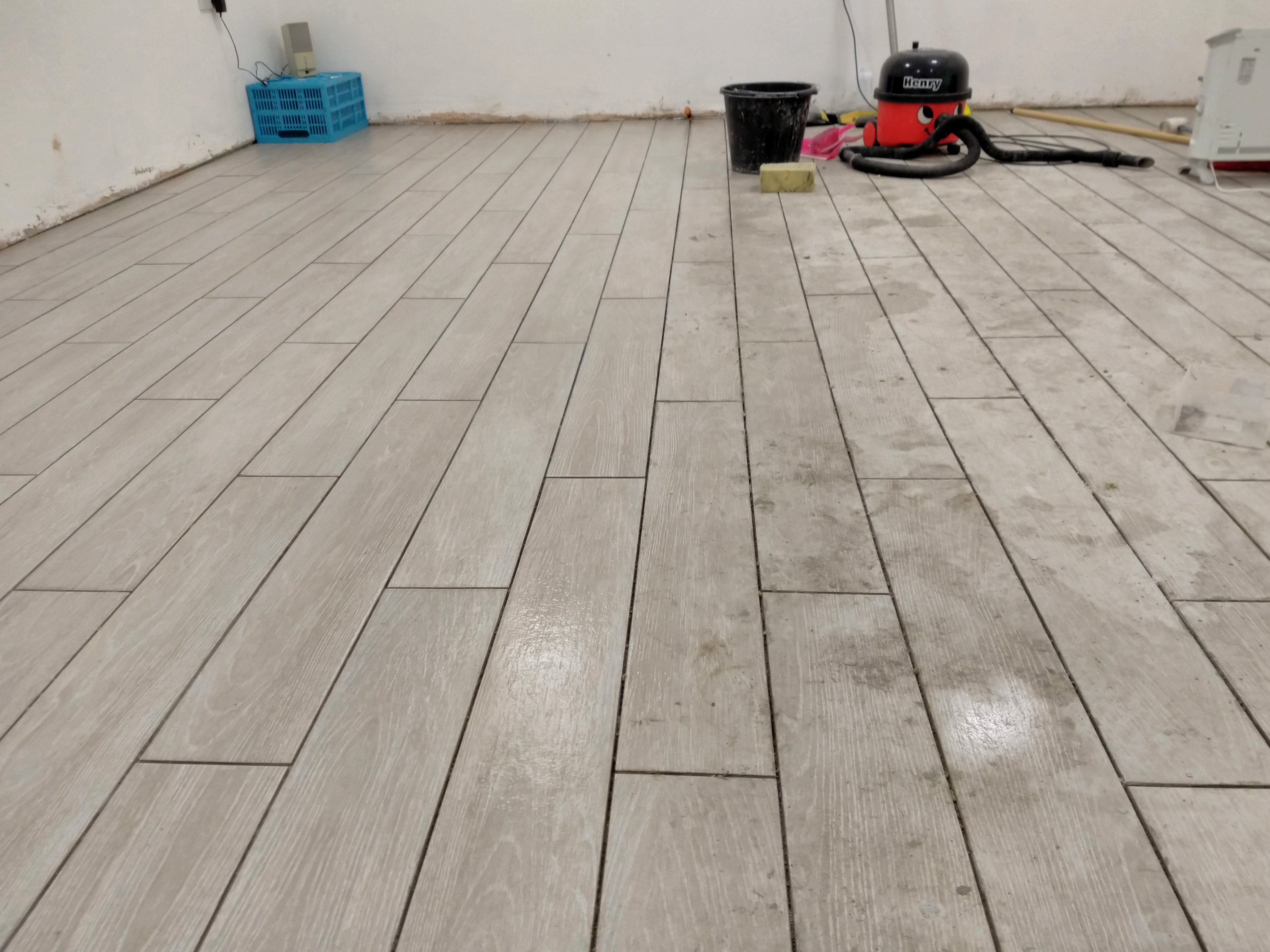
By the time I was done, the wire brush was ready to be thrown out.

Grouting
Finishing up the floor, we added grout to fill up the space between the tiles. This was yet another case of “put powder in bucket, add water, mix”. We re-used our floats to squeeze the grout into the gaps, and did our best to sponge-clean the excess.
After covering the entire floor, we walked around with a little bit of grout, hunting down air bubbles and gaps, and fixing them up. This all went quite well, and it looked really nice.

Cleaning the grout residue took a couple of attempts. We’d purchased a grout residue cleaning product for this (earlier tried for mortar residue cleaning), and followed the instructions on the bottle: dilute in water, mop the floor with it, and after at most 10 minutes, rinse with lots of water. The residue only properly shows up when the floor is dry, so it’s not really possible to tell whether you’ve cleaned it while it’s still wet.
It turned out this method failed utterly; The removed residue remained in the water, and simply settled down again when the water evaporated.
This working method, of course, involved a lot of manual labour. We got an “emulsifying pad” (a slightly abrasive sponge attached to a plastic handle), and some rolls of paper towels.
The process looked like (wearing latex gloves):
- Lightly wet a few tiles with a normal sponge
- Dip the emulsifying pad in diluted grout residue cleaner
- Scrub wet tiles with emulsifying pad
- Rinse with fairly wet normal sponge, then rinse the sponge again
- Wick away the water with paper towels, getting the tiles as dry as possible
- Repeat for further tiles
The fifth step was important; it ensured the grout residue dissolved into the water was immediately removed, instead of being allowed to settle down again as it dried.
This progress shot shows the difference between dirty (left), and cleaned (right).
With that done, the tile floor was finally finished.
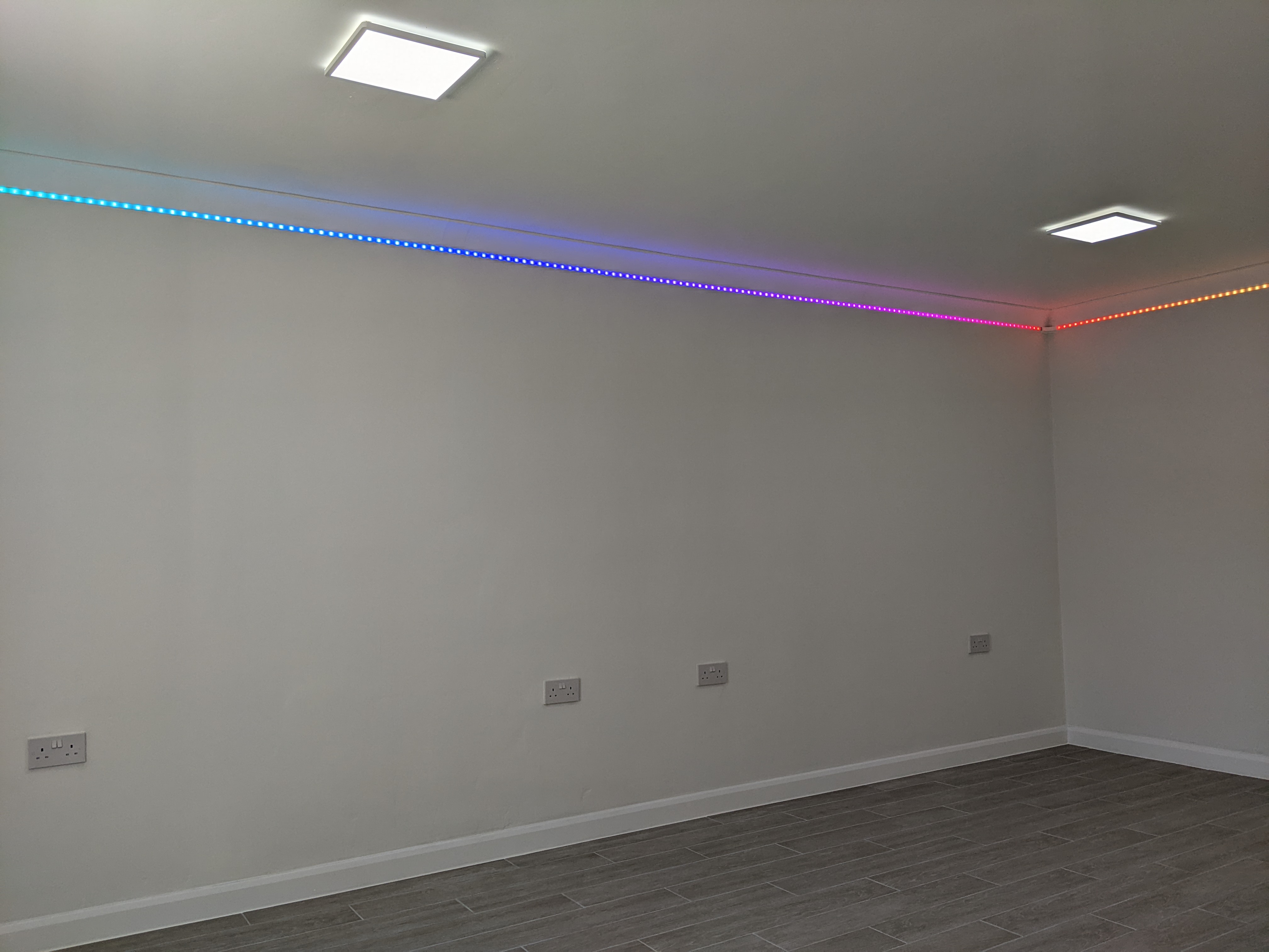
Fancy LED Strip Lighting
Before we began flooring, I briefly attempted installing the LED strip lighting. Per a friend’s advice I decided to use “very high bond” (VHB) tape, which would glue the aluminium profile to the wall. That initial experiment was cut short by the paint pulling right off the plaster.
After the flooring, the paint had had a good month to dry and cure, so it was actually ready to receive the VHB tape.
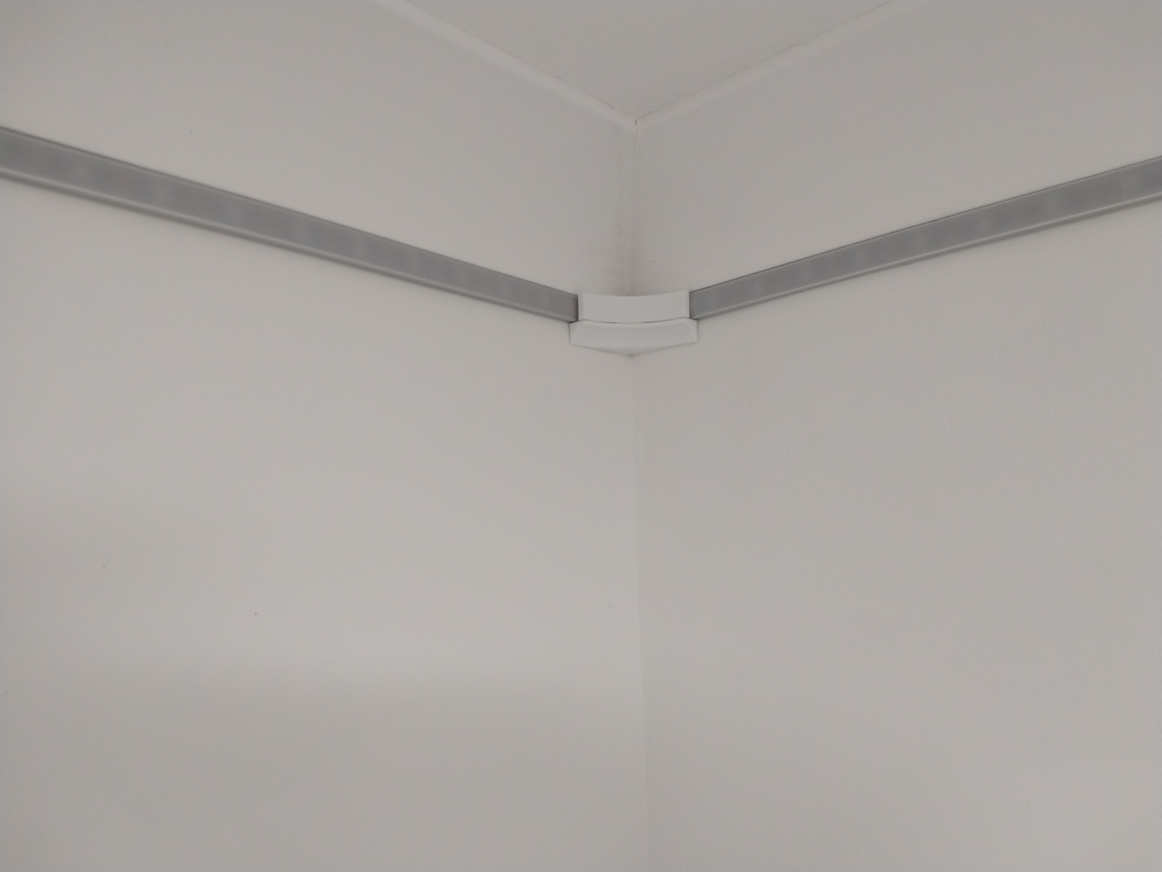
I hung all the aluminium profile sections in about 2 hours, including cutting a few of them to the right size. I fixed 3 bits of tape on each metre-long section of profile, and pushed it firmly in place beneath the coving.

I do like hiding “Easter eggs”. Who knows, if someone takes these LED strips down one day, they might chuckle. In any case, the idea makes me chuckle.
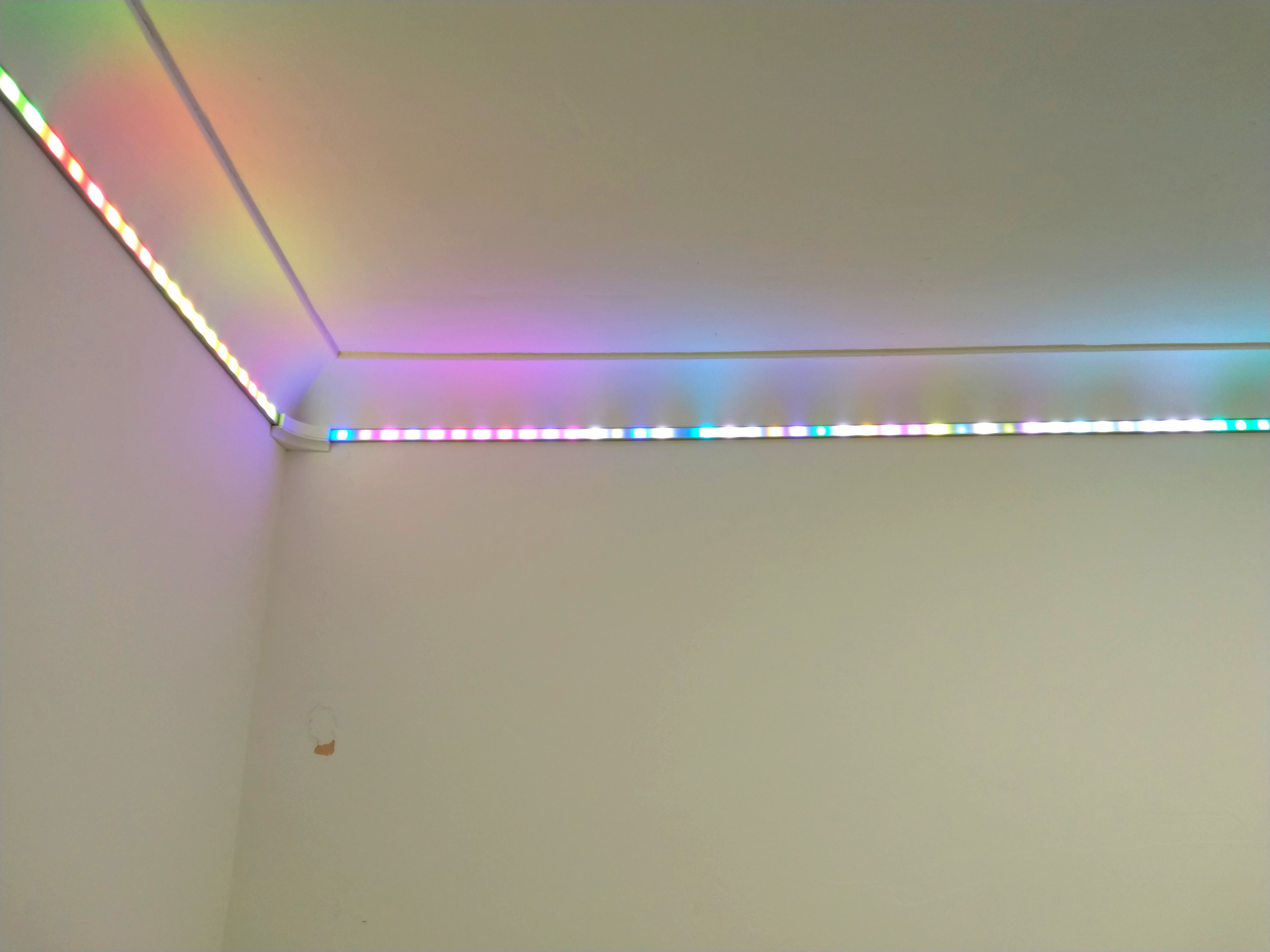
The APA102 LED strips I picked came on reels of 5 meters each. The strips have a tape backing, so they’re nice and easy to install: peel the back off and tape it into the aluminium profile.
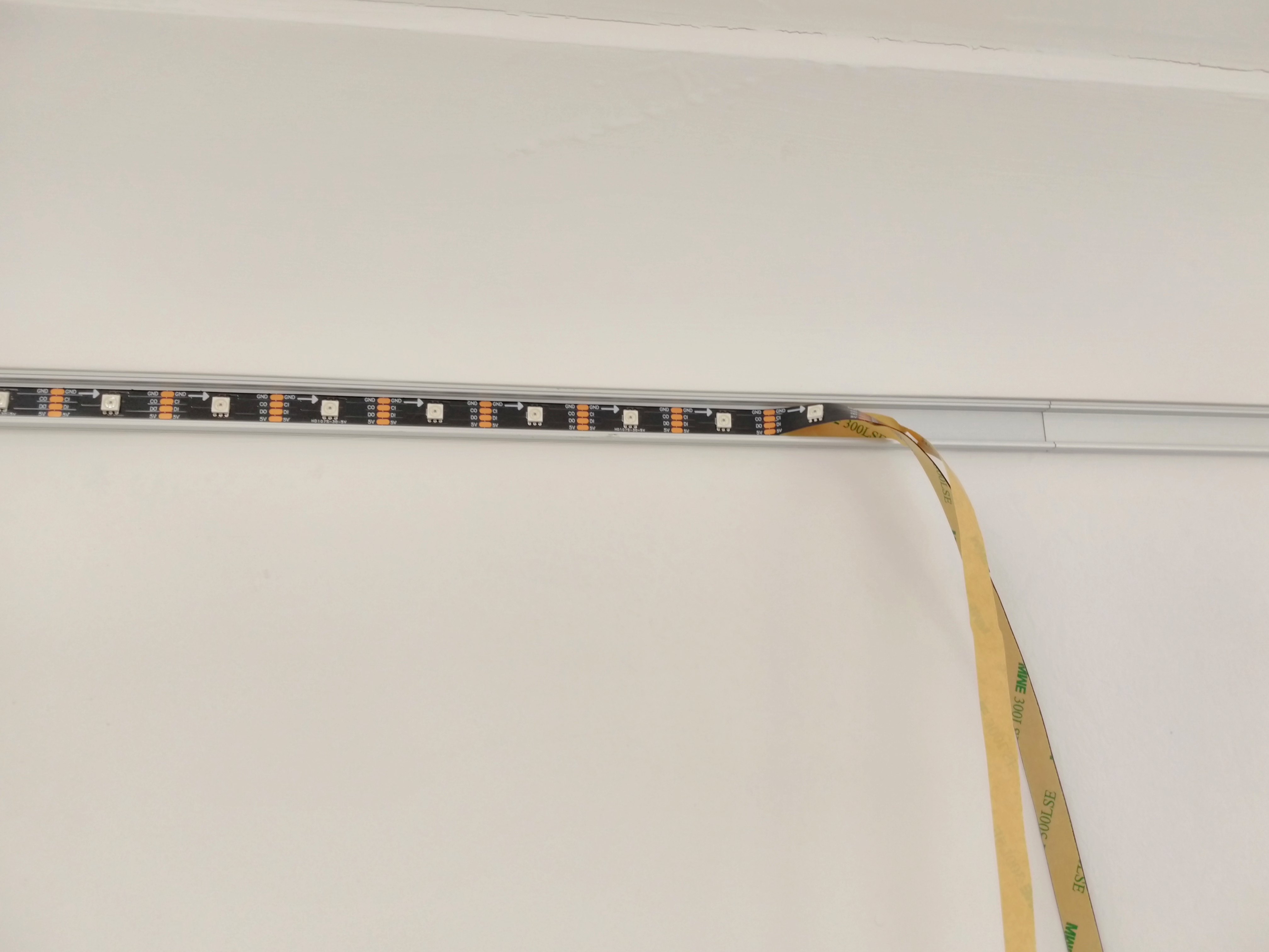
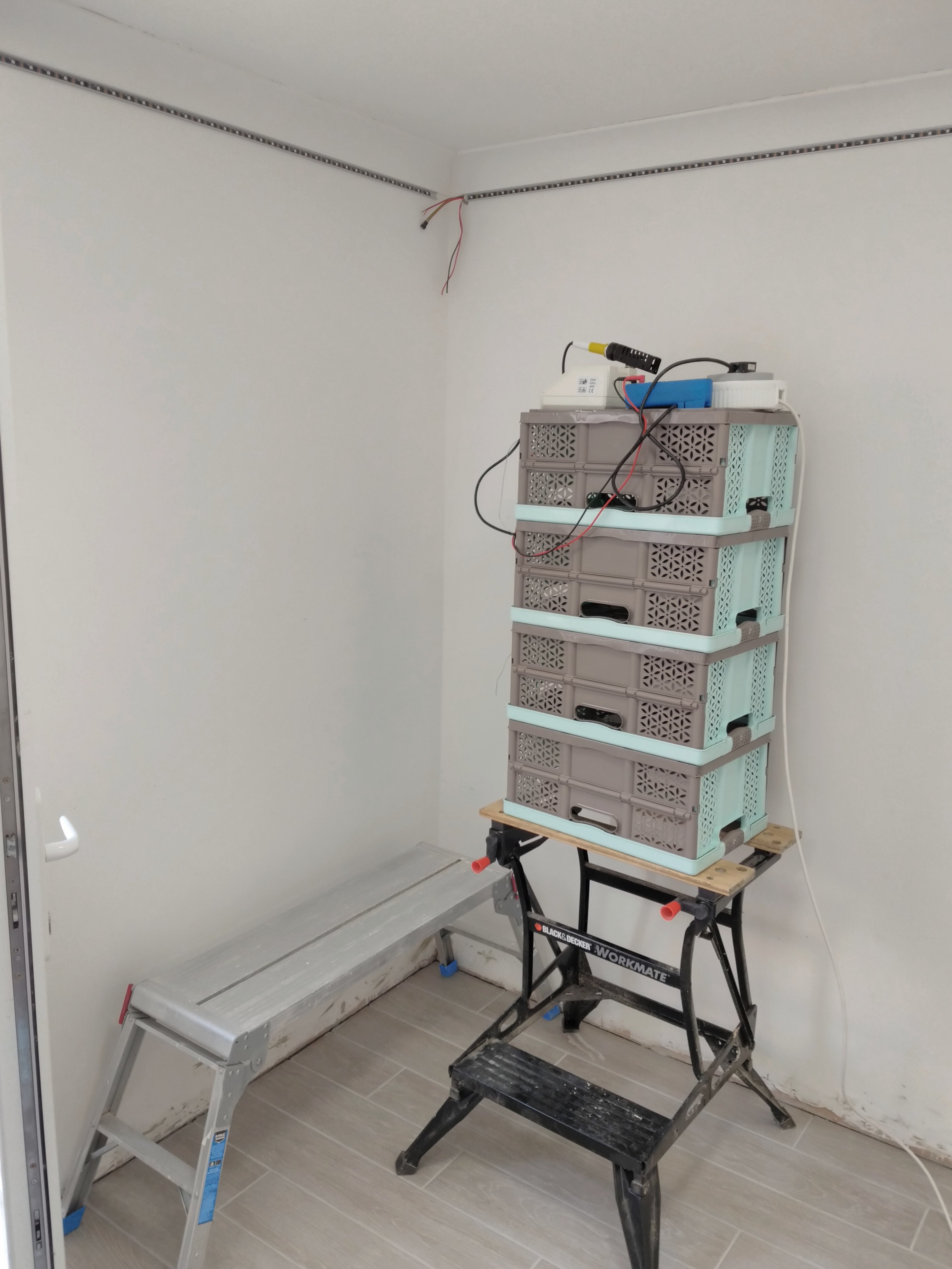
The longest walls in this room are just a bit over 5 metres long, so I had to splice sections of LED strip from two reels. I had to improvise a bit to do the soldering work right under the ceiling, that is, to get the soldering station at height:
After making all the connections and tucking the wiring away as much as possible, I installed the diffusing covers the aluminium profiles shipped with; they clicked and slid in place without any trouble. I positioned them to bridge sections of aluminium profile, helping to keep them in line with one another.
I designed some 3D-printable corner pieces to hide the wiring and the ends of the aluminium profiles in the corners. I put these up with some more VHB tape.
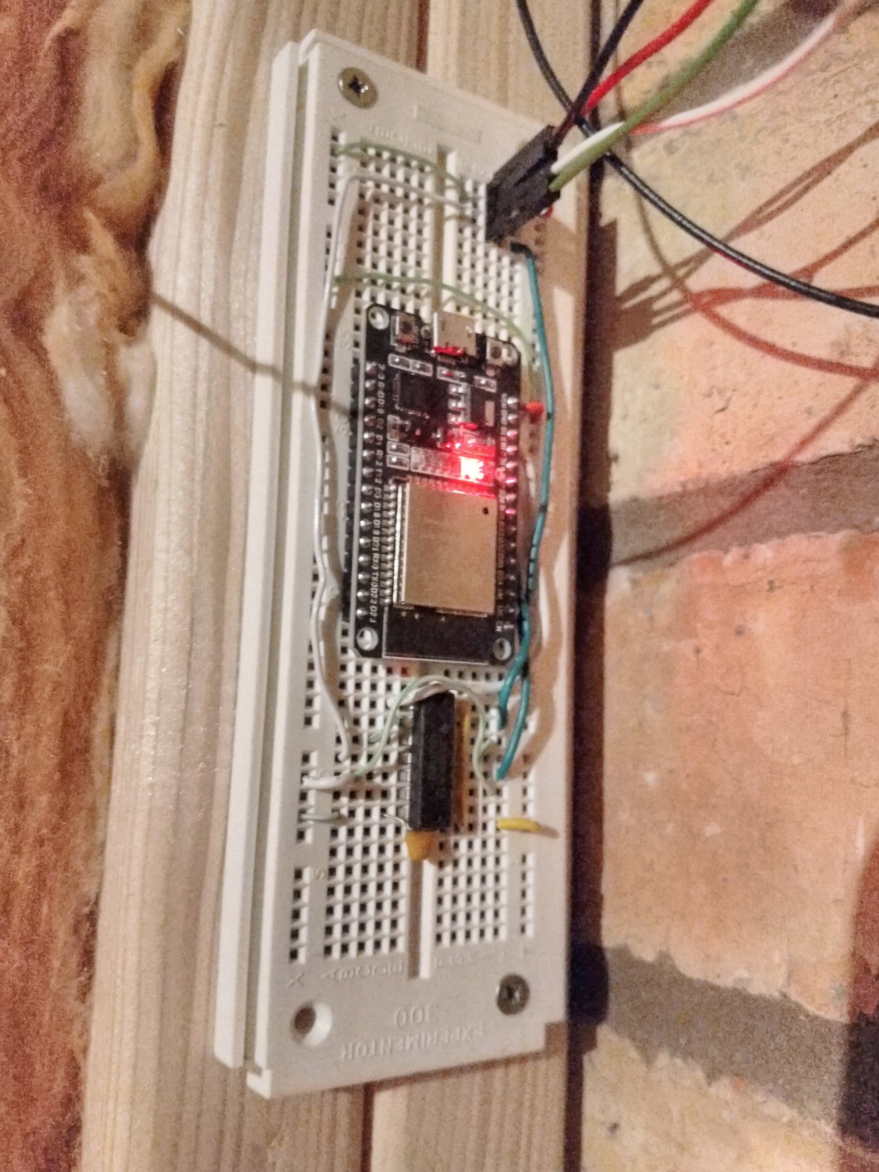
We had a couple of ESP32 development boards laying around. These are micro-controllers with wireless networking capability built in. They’re very popular with electronics hobbyists to make devices that connect to the internet (or, preferably, just to the local network) to do all sorts of fun stuff. There is a big ecosystem of software libraries, making common tasks (like controlling LEDs) simple. So naturally, in the evening after I finished installing the strips, I loaded up a library called “FastLED”, plugged it into a breadboard, and hooked it up.
I turned it on and… the breaker for the lighting tripped. Not a great start. Okay, I have to admit that I already knew this would happen, having tried a power-on test of the power supplies.
The LEDs use 4 Meanwell LPV-100-5 power supplies. Upon powering up, they each charge a large capacitor; this capacitor component helps produce a stable voltage of 5 Volts during variable power demands. Charging a capacitor very briefly draws a large amount of current, known as the “inrush current”. Multiply this current by four, and the spike is enough to trip a regular “B6” lighting breaker, apparently.
Anyway, I knew this would happen, so I reset the breaker twice in quick succession until it stayed on. I would address the inrush current problem later; after all, the LEDs can be fully switched off in software, leaving mains power to the power supplies switched on.
The LEDs then lit up, and more or less displayed the scrolling rainbow pattern I’d quickly programmed them to. I say “more or less” because it was clearly not quite right; there seemed to be data integrity issues. That said, I was rather pleased that they lit up and clearly got data going through them.
Taking a more careful look, none of the LEDs showed signs of receiving too low a voltage. This would be shown by LEDs never showing certain colours like blue, but tending more toward just red. This is because red LEDs have a lower voltage drop than blue ones, but that’s another story. Thankfully, I didn’t observe such behaviour at all, so at least the power system wasn’t at fault.
I realised that the micro-controller uses 3.3 Volt logic levels, while the LED strip expects 5V. So the micro-controller delivered clock and data signals at the wrong level, causing the signals to be misinterpreted (logic ones and zeroes) more often than not. Two days later, I added some circuitry to shift these logic levels up to 5V, using a 6x Schmitt trigger inverter chip I had in my components stock. The theory proved correct, and I got to stare at glorious scrolling rainbows at last.

I intend to make a custom circuit board and enclosure for the controller, but for now, it looks like this: a solder-less breadboard with stuff plugged into, and long dangling wires leading to the LED strip through the wall:
After showing off my work on a few Discord servers I’m on, someone mentioned a piece of software called “WLED” to me. I was planning to write my own control software, as well as various integrations, but of course the internet was 20 steps ahead. WLED is firmware you install on this ESP32 micro-controller. It controls the LEDs, and provides a web interface to configure them to your heart’s content. It comes packed with a bunch of pleasing light effects, preset functionality, and a whole bunch of additional ways to send it light data. In short, everything I could possibly need to get the maximum amount of use out of these LEDs.
It is now connected to our WiFi network. On a desktop PC, we can play music while running a piece of software called LedFx to visualize the music on the LEDs. It makes for a pretty immersive experience. I feel like I’ve only scratched the surface of the possibilities. I’m even using an entire wall as a progress bar for an ongoing 3D printing job.
I fixed the inrush current problem using a device aptly named “Inrush current limiter”. This is installed between the light switch and the junction box for 4 power supplies. The limiter, on power-up, routes the current through a current-limiting component (not a simple resistor but something called an NTC Thermistor; less resistive as it gets warmer) for the first 300 milliseconds of being powered on, and then switches it to a direct connection right after. I installed this in another junction box that would fit it, and it solved the problem beautifully. Turning on the LEDs via the light switch now no longer trips the breaker.
Finishing Touches, More Paint
While tiling the floor, we spilled small bits of mortar on the walls. During my first attempt at installing the LEDS, I ripped a few bits of paint from the plaster. Because of issues like these, we decided to do a bit more painting to finish things off.
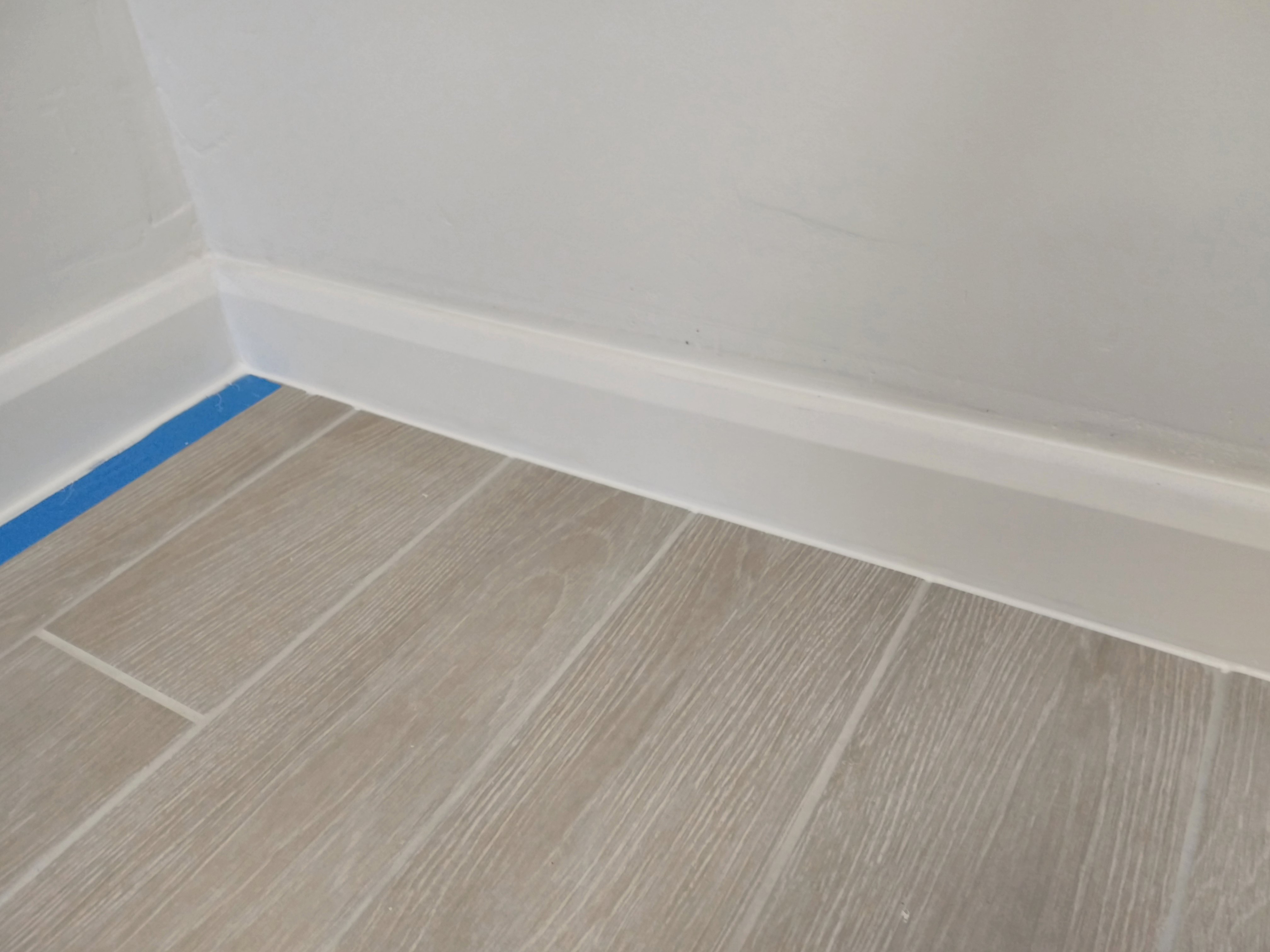
We installed skirting board, making the transition from wall to floor look nice and clean.
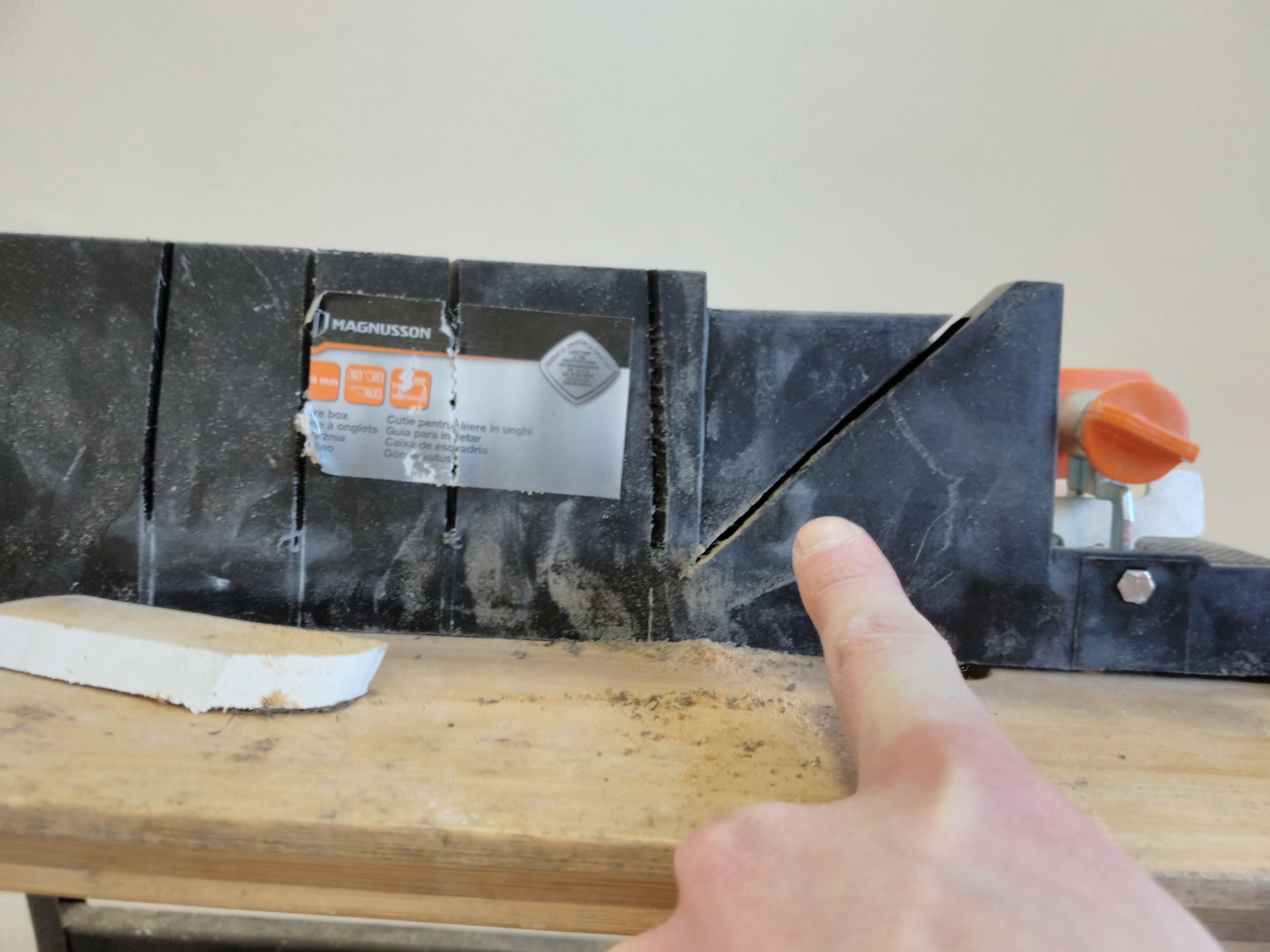
Like coving, skirting board requires a mitre box to cut the 45 degree angles for the corners. Our skirting board is quite tall, so I 3D printed a custom mitre box that extended along the full height. This, as expected, quickly snapped. We spent a good half hour considering options, and eventually spotted that the mitre box we owned actually supports cutting skirting board, just not in the way we expected. You have to lay the board flat and use the saw at a 45 degree angle.
Yours truly was on board cutting duty while Brittany glued the skirting board against the wall, which made it a pretty quick job.
We then moved on to preparing the wall for a new coat of paint. We removed mortar spillage, and sanded around spots where plaster was visible. On these spots, we applied a mist coat to allow the normal paint to stick properly.
Next, we put masking tape on the floor along the skirting board, and applied two coats of white paint to that skirting board. It came with a primer coat, so that saved a step.

A day after, we covered the skirting board, sockets, and LED strips with masking tape, ready for wall painting. This took two coats with paint rollers and brushes for the corners, and came out looking pleasantly smooth.
Finally, we filled the gaps around the skirting board and under the LED profiles with silicone sealant. On the floor, we applied masking tape a few millimetres away from the skirting board to create a straight cutoff for the sealant. The sealant was applied with a sealant “gun”, and smoothed out with a fingertip.
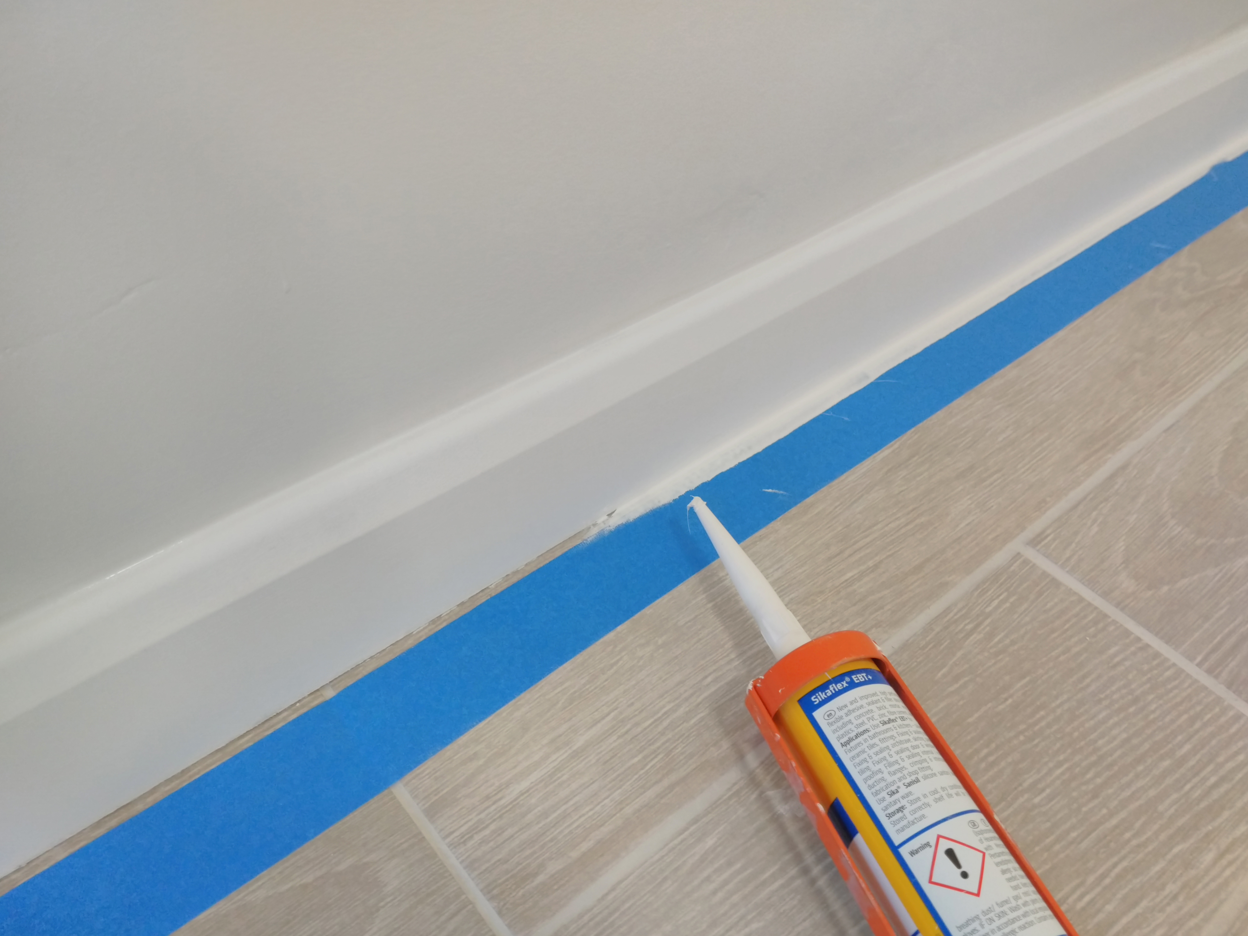
The LED profile gave me a bit more trouble to get right. It was very tricky to mask it just right to prevent getting sealant on the front of it. I tried reducing the amount of sealant used, but it didn’t help much. In the end, I just let it dry with spills on the front. The next day I removed the diffusing covers and cleaned off all excess bits of sealant with my fingertip.
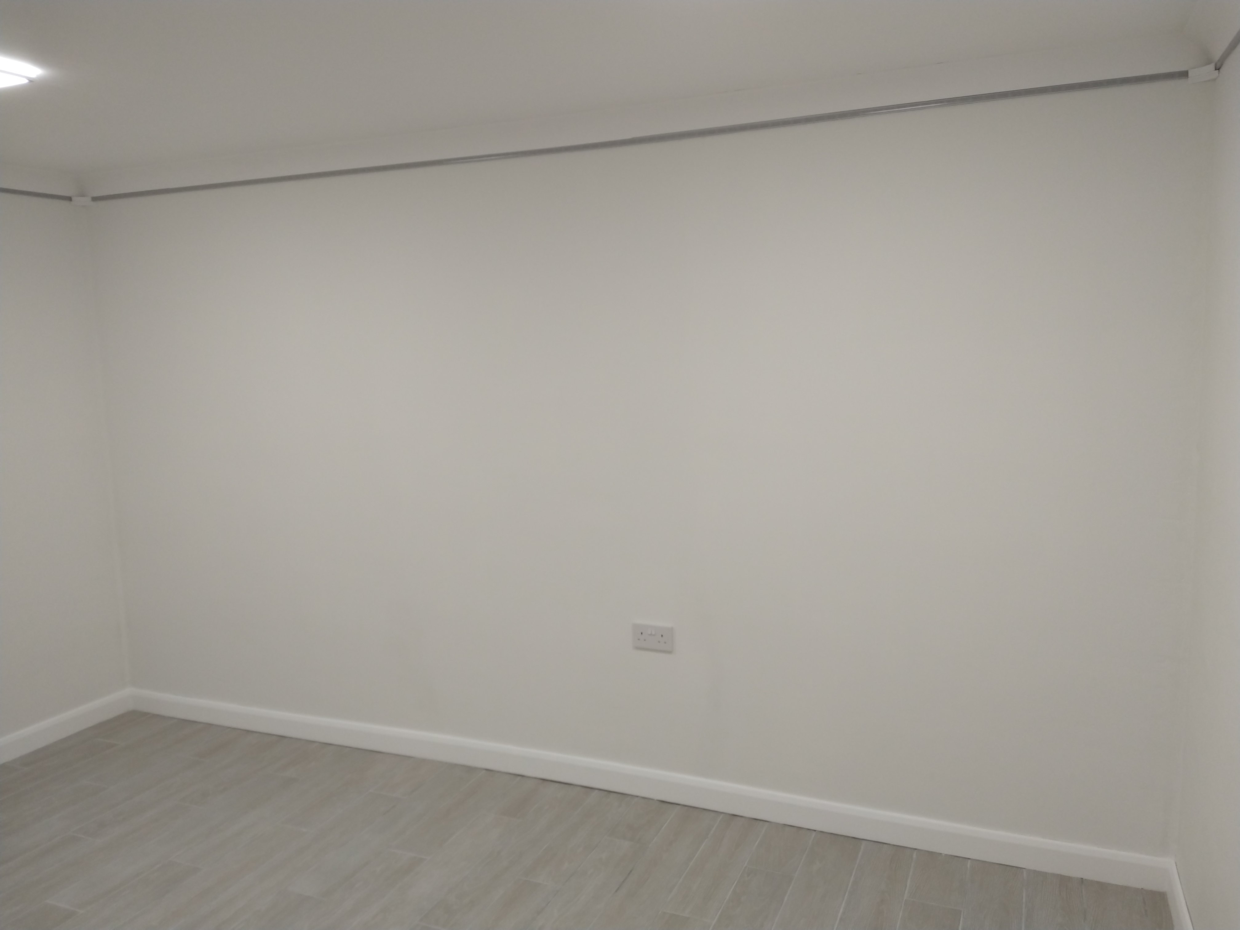
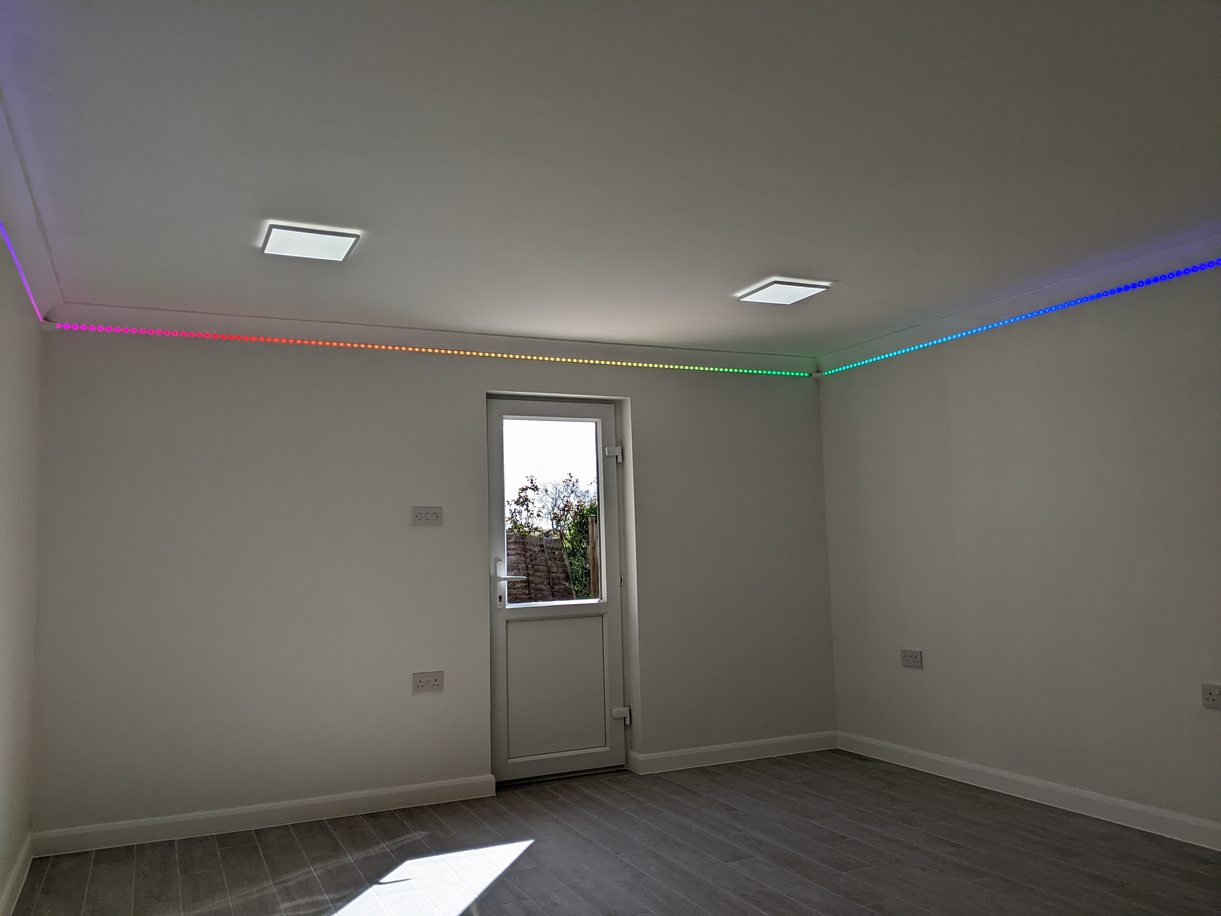
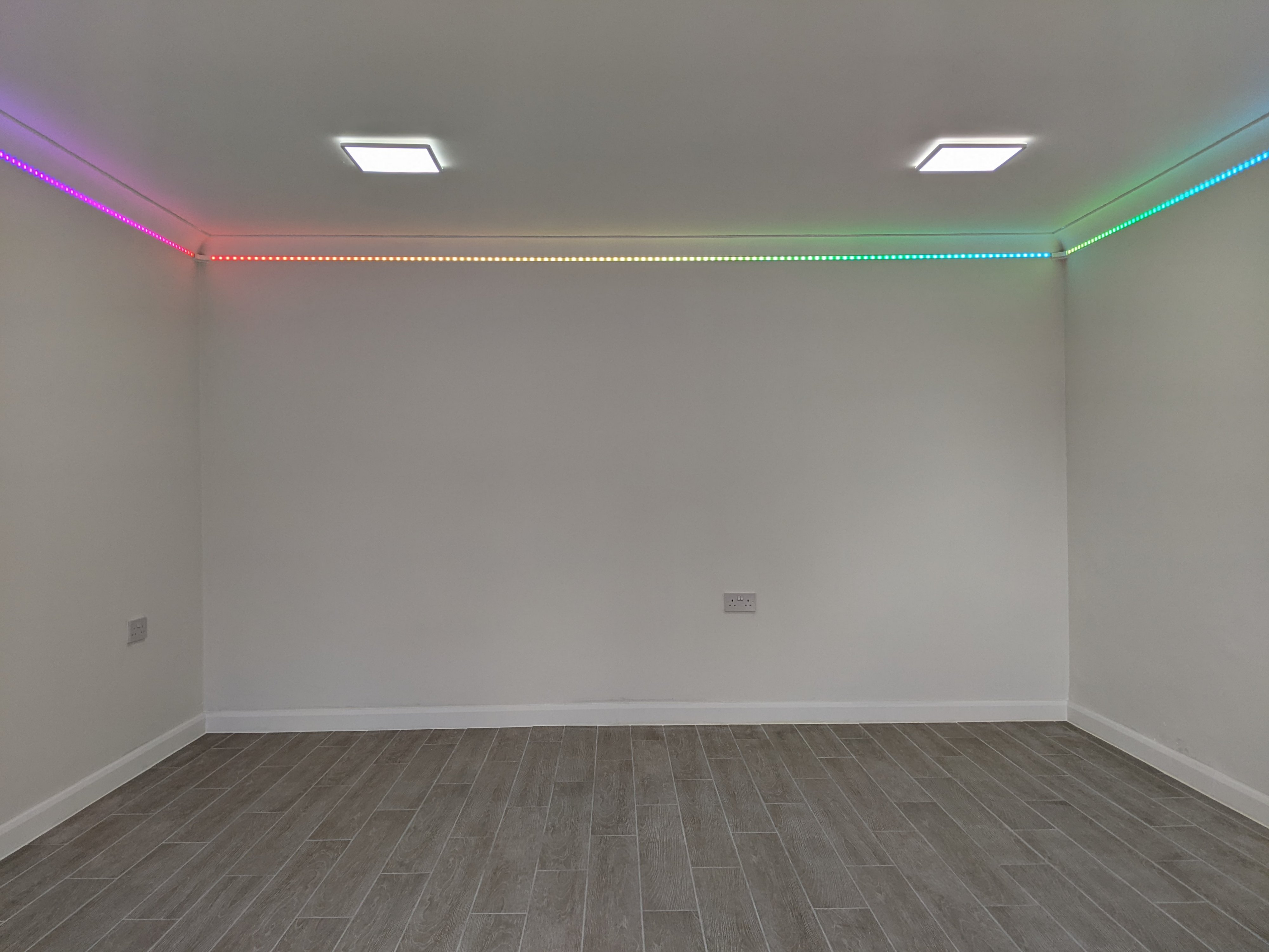
Inside: Finished!
Here are a few more photos of the finished conversion. The camera made some automatic adjustments that makes the tile floor a darker grey than it is in real life. The previous pictures are more representative of the actual colour of the floor.
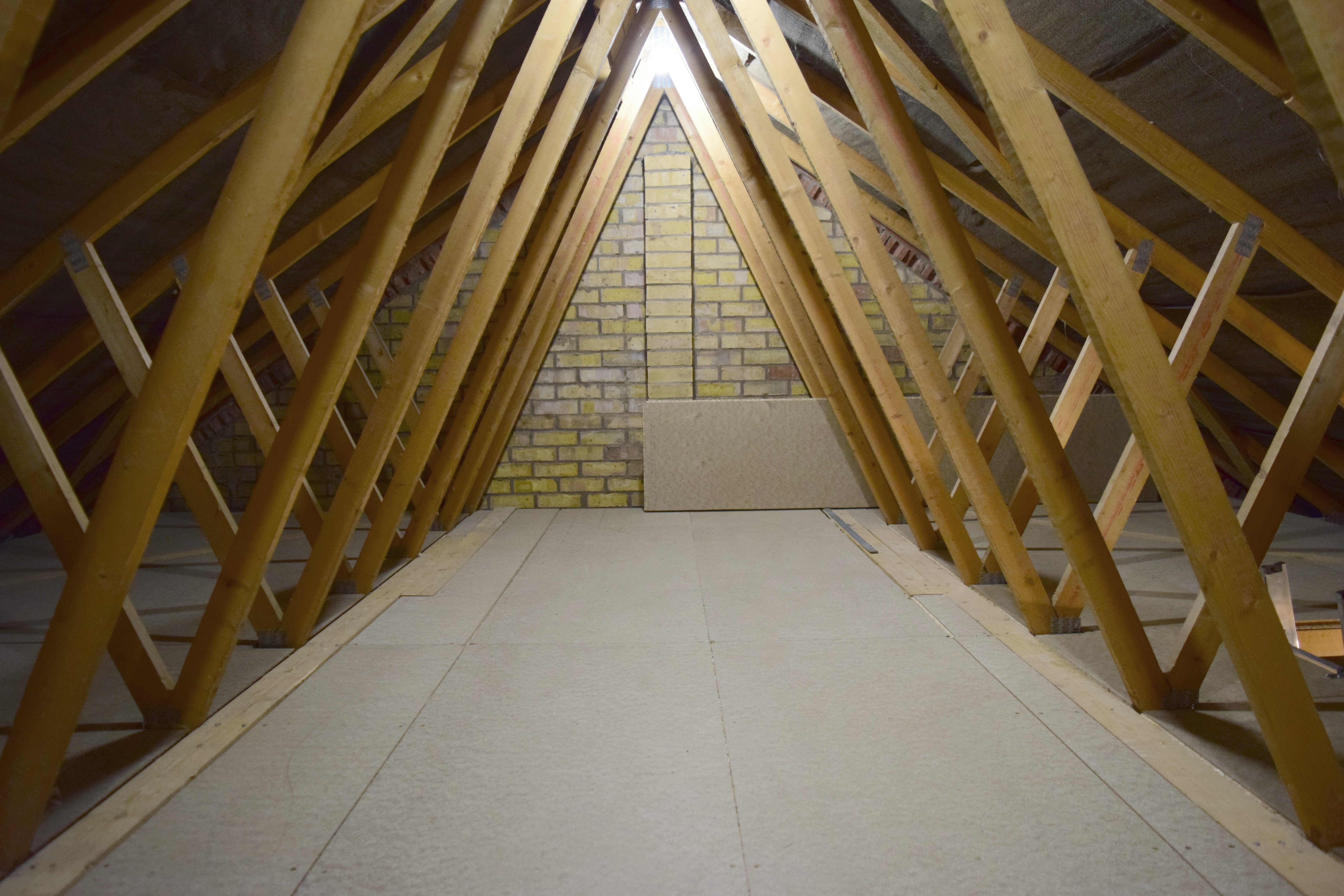
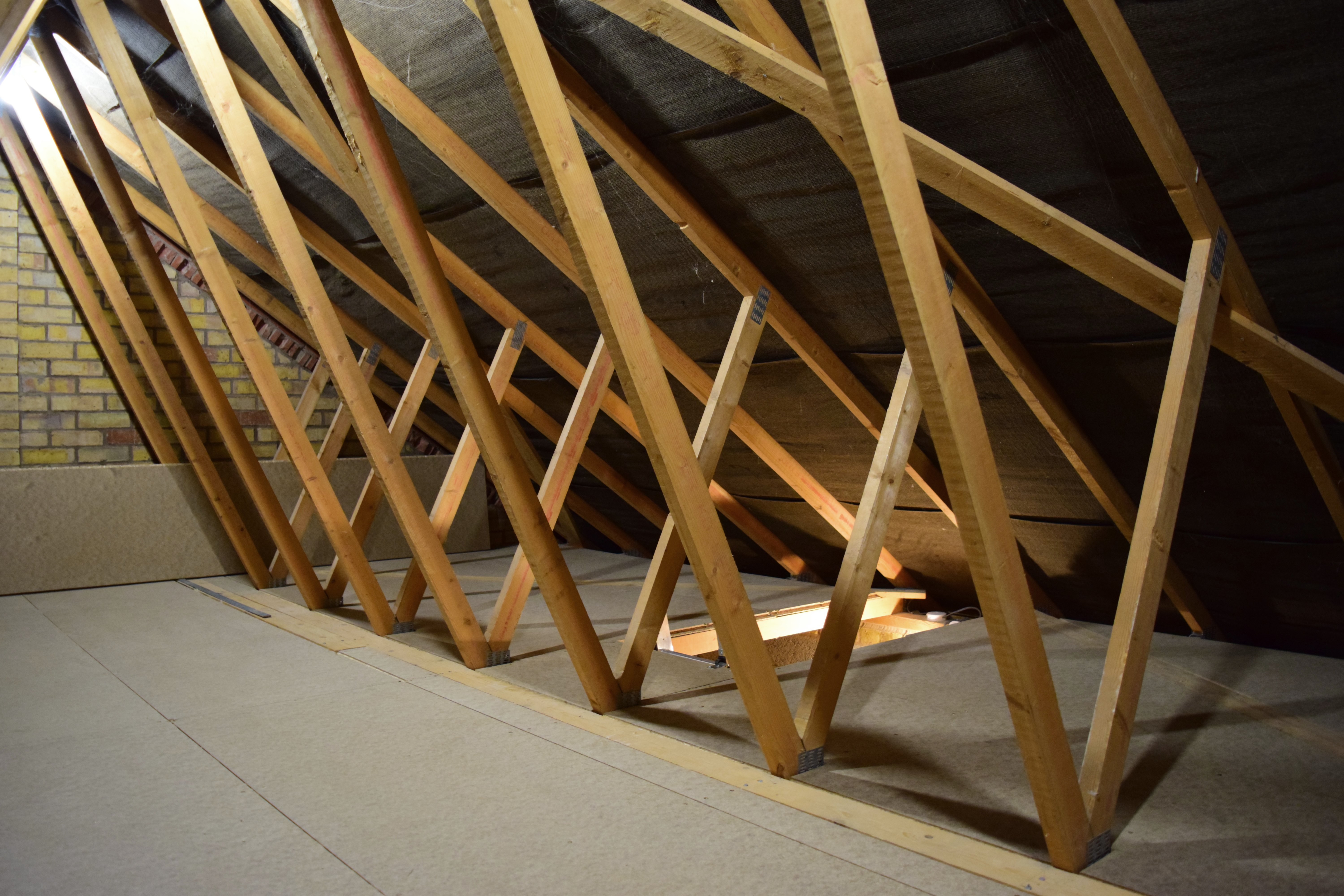
Flooring the Loft
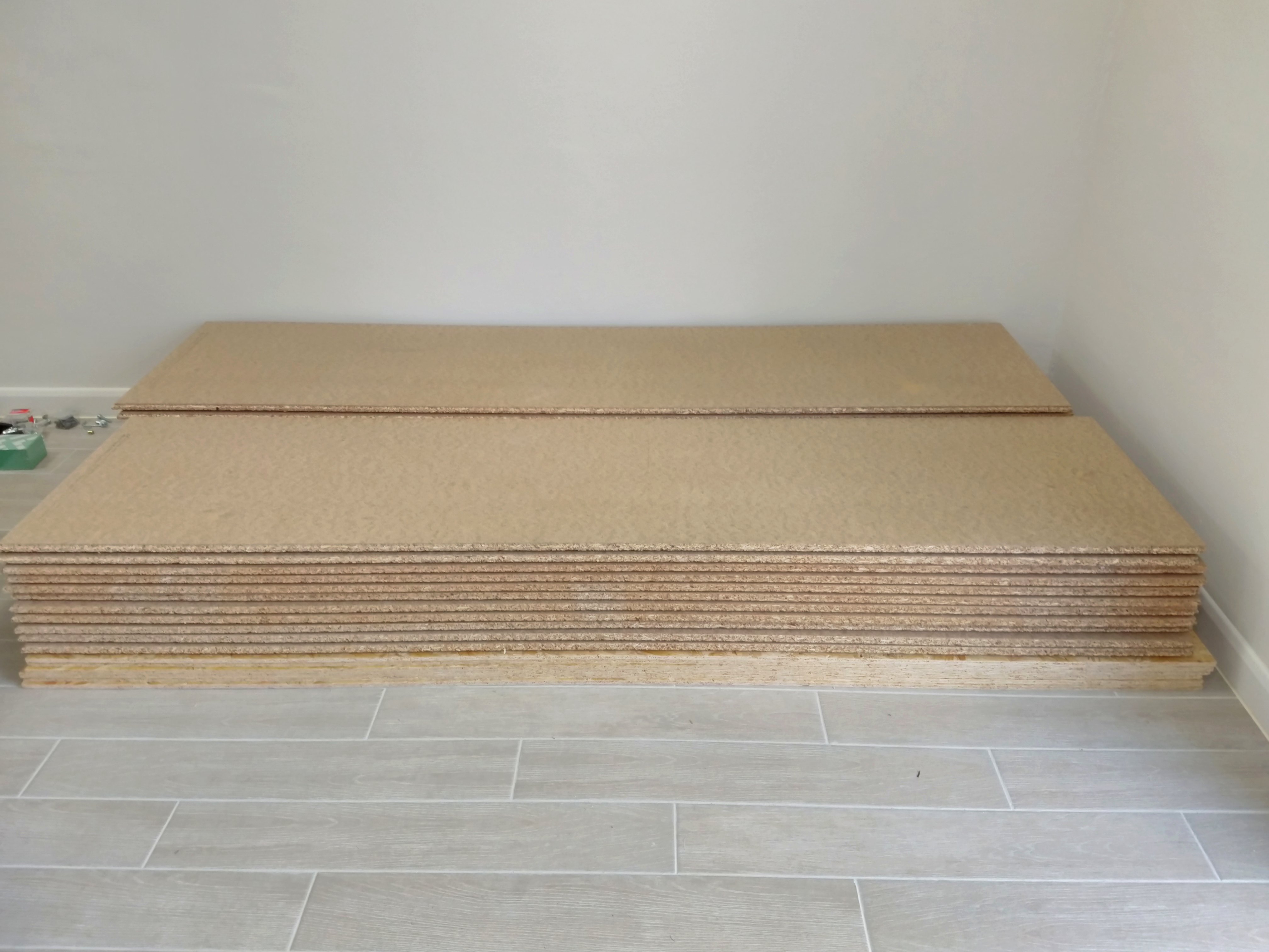
We were pretty ecstatic about finally being able to use the new room, but our conservatory was still filled with a whole bunch of assorted stuff that needed a place to go. We ordered a bunch of 22 mm thick fibreboard to install as flooring on top of the garage’s joists, opening up a whole lot of storage space.
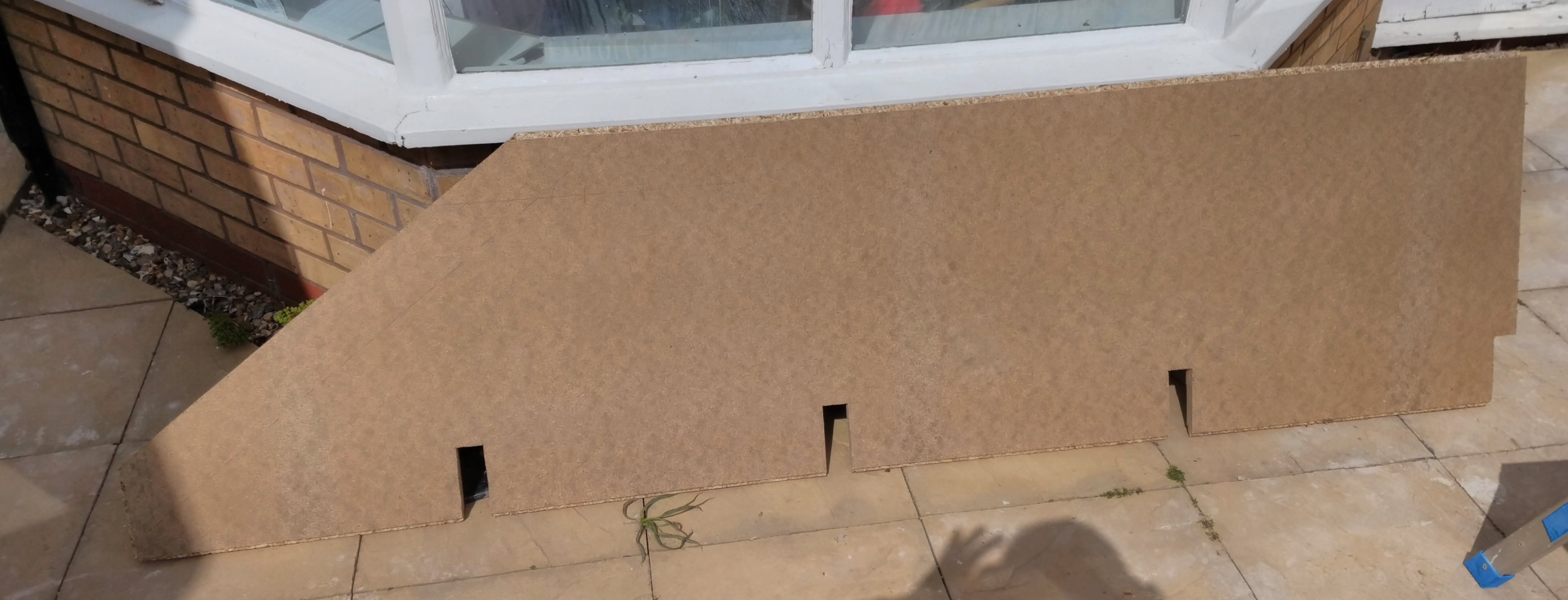
The roof construction is a so-called “fink truss” design, which means trusses are in the way all over the place. In addition, there are a few diagonal planks on top of the joists to reinforce the structure. We wanted to use all the available space, so I had to work around these to cover the full area.
Here is one such board I cut up to fit around all these obstacles.
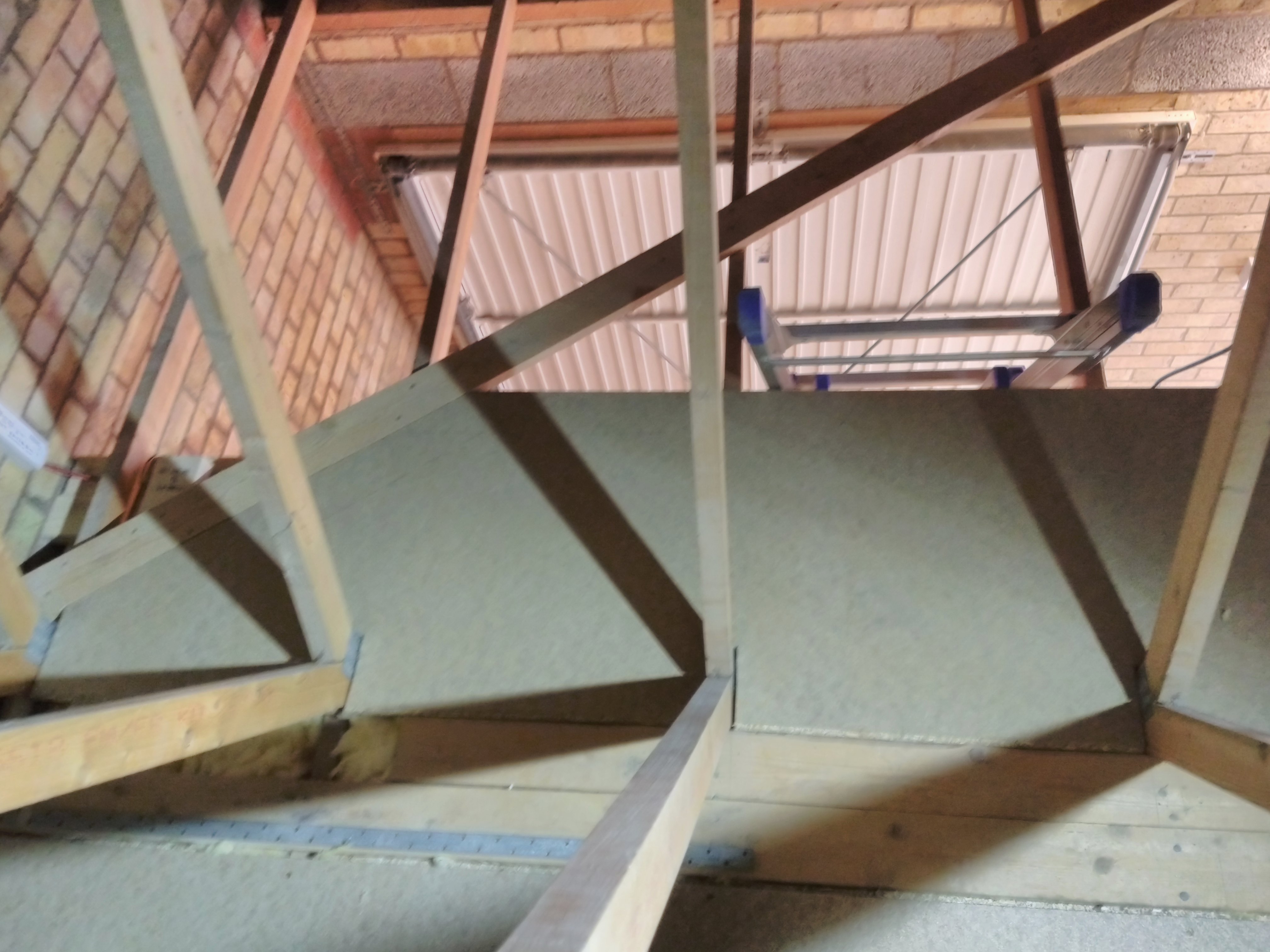
The majority of the effort was moving the boards up to the loft, and moving them around between the trusses. After the widest section in the middle was ready, I moved the cutting setup there, reducing some of the moving around. It was still plenty of work to shimmy the boards into the “V” shape of the trusses, then through the other end.
Anyway, without further rambling about how moving large objects through a bunch of obstacles is annoying, here are some photos I took after finishing the floor (and also, lighting).

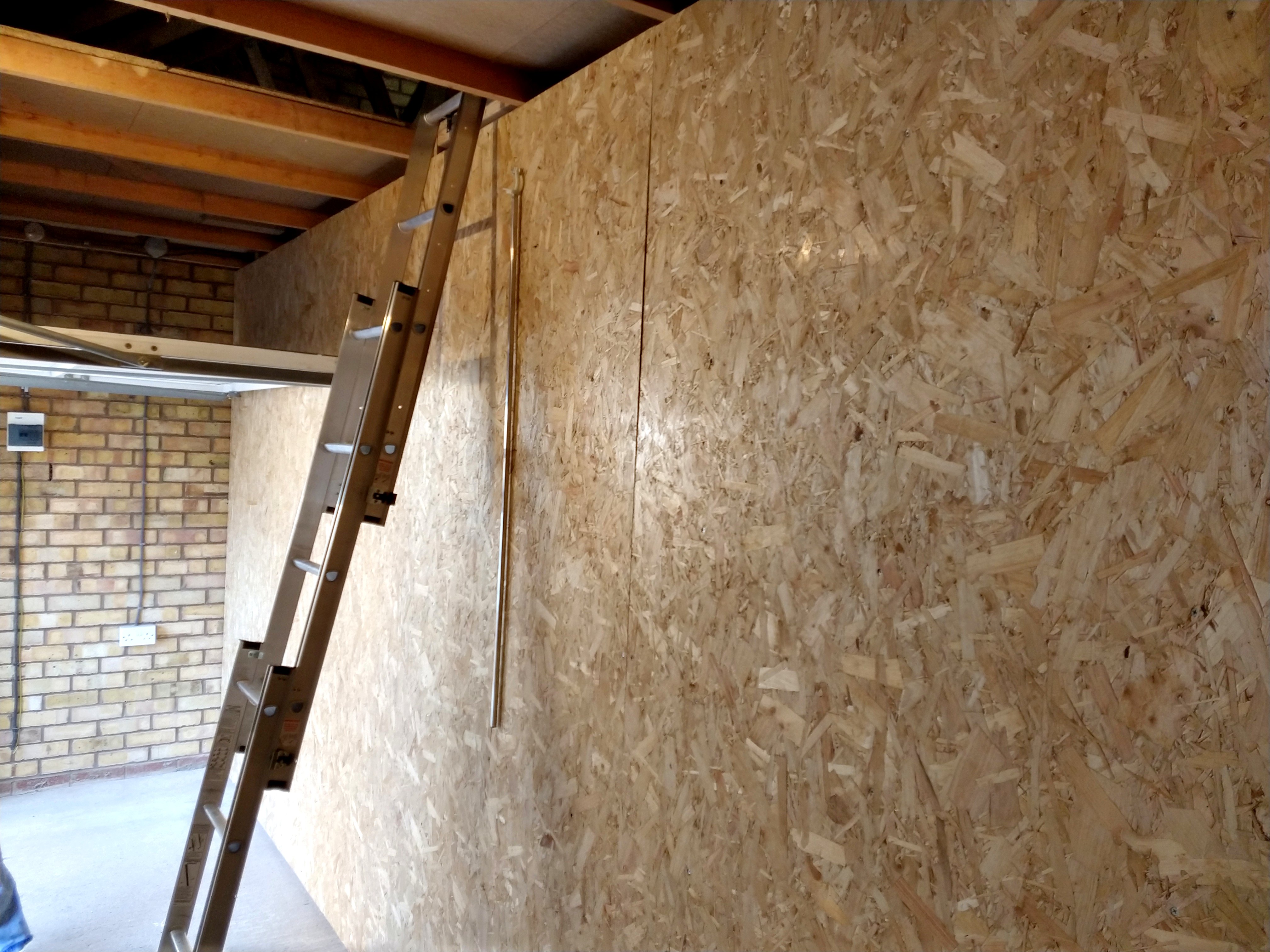
Lastly, I installed chipboard on the remaining exposed side of the dividing wall. I re-used the same foot lever thing from the plaster boarding project to push the chipboard up against the joists, which made this a quick job.
That’s it!
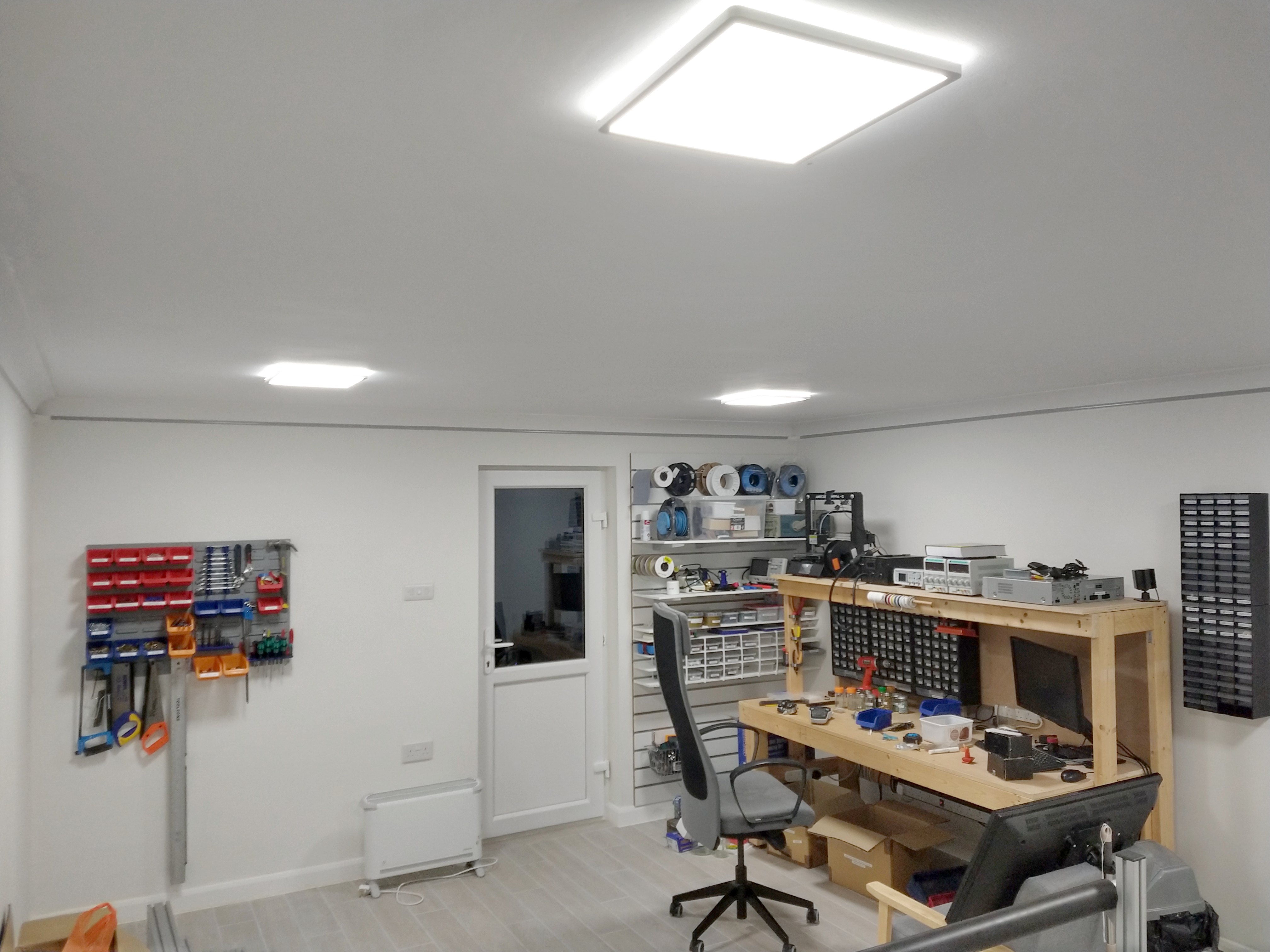
We’ve both been quite busy getting set up in our newly finished Nerdhub. I’ve rebuilt my old workbench and installed a section of slatted wall with shelving for various electronics-related things. I’ve also installed some wall-mounted component trays, and some panels with detachable bins and tool holders for various screws, and, well, tools.
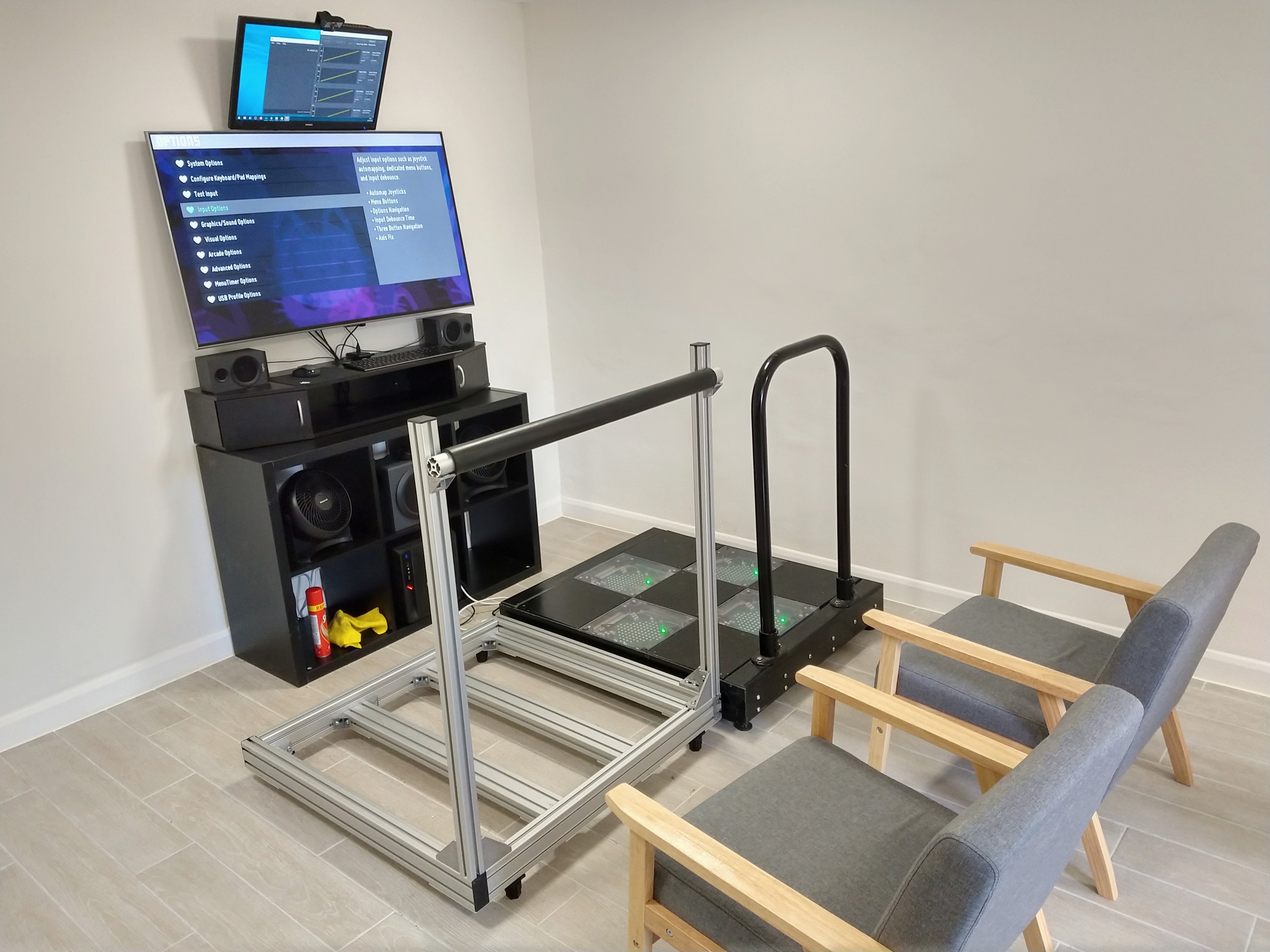
Brittany set up her dance gaming corner with her existing dance platform, a TV, speakers, fans, and furniture to make it all look great together. There are also a couple of chairs for guests to chill out in while someone’s sweating on the dance pad.
Here are a couple more shots of what we’ve got going so far.
Thank you for looking through our project, I hope you found it interesting!
[Edit] Thanks to my dear sister Maris for pointing out some ~34 (give or take a few) tpyos*, now fixed! <3
* Yes, that’s the joke