Hacking a line-in socket into an 80s radio and cassette player
A few years ago, my grandmother gave me one of the old radios she had lying around the house. My late grandfather’s hobby was participating in radio quizzes, which led him to win a lot of radios; I assume this was one of them. The radio was manufactured in the early 80s, so the guts are relatively easy to tinker with; everything is on single-layer PCBs.
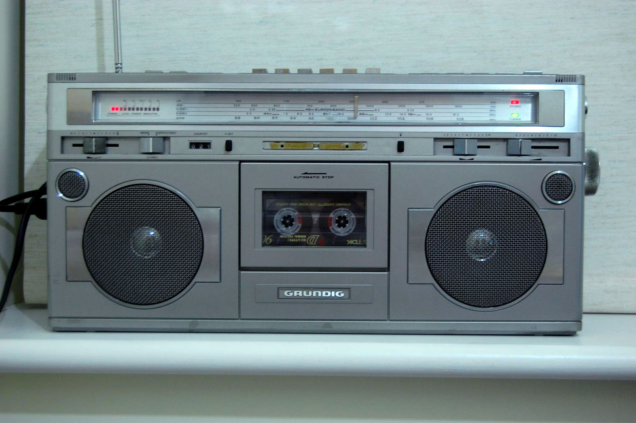
I realised that the audio quality of this old boy was really decent, so it would be a waste to just let it sit in a cupboard. I don’t generally listen to the radio that much, and I don’t exactly have a big collection of music on cassettes either (and if I did, I’d digitize it anyway). To really get some use out of it, the most logical thing would be to have a line-in, letting me hook up a phone or whichever external audio source.
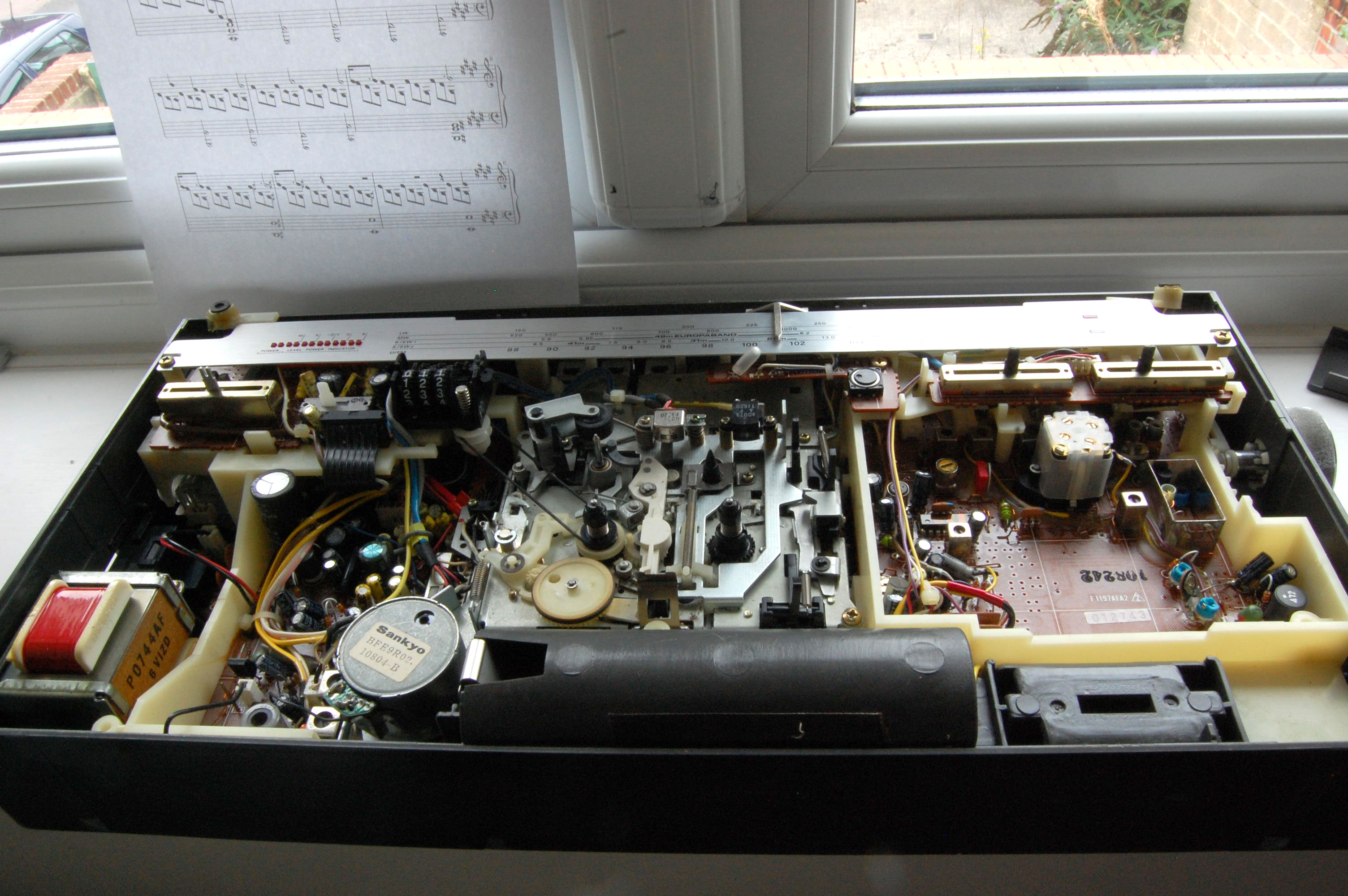
So, I set to work, opening the machine up.
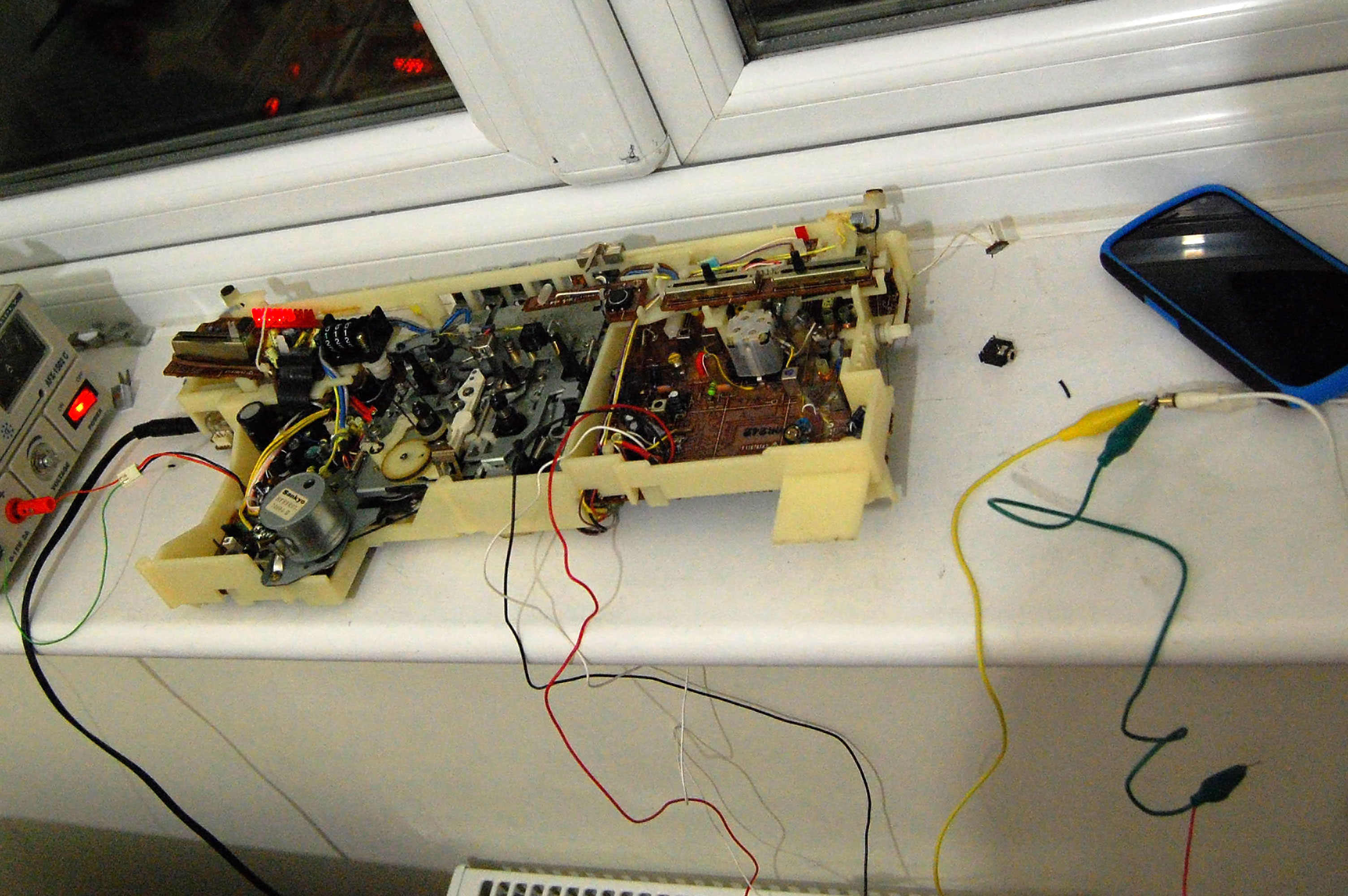
I used a Korg Monotron as a relatively cheap audio source to test points where I could introduce the line-in to the system. If I made a wrong move, I could blow up my phone, so I didn’t exactly want to use that.
While testing, I didn’t want to risk electrocution by using the on-board transformer, so I wired up a bench power supply instead. I also had to use the headphone output to test audio output, as the speakers were glued to the case I took off – I had to disconnect them.
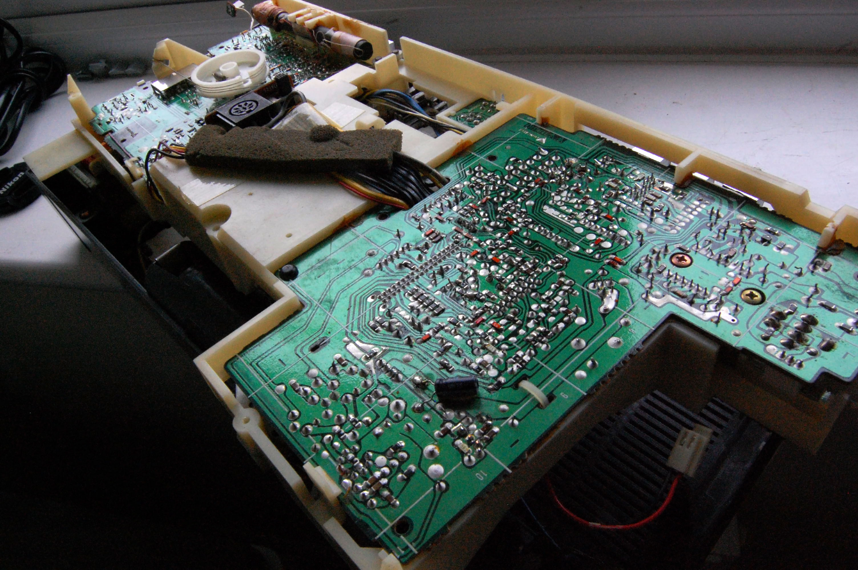
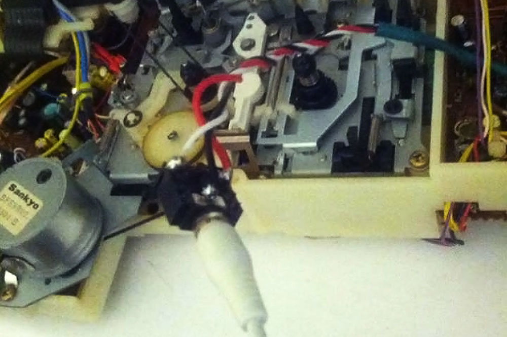
The PCB really didn’t have many useful markings on it, but I managed to locate the cassette player’s audio output. Experiments showed I’d have to press the play button – thereby setting in motion the rattling cassette mechanism – to get any sound through. Not an option.
Eventually, I spotted similar wiring coming from the radio PCB. For this to work, the radio has to be turned on, which, naturally, causes the radio to start playing. However, there are buttons to select the radio band you want to use (FM, AM, and a couple more obscure ones). I found that I could trick these buttons, allowing no band to be selected, that way stopping any radio audio from coming through. Bingo!
At this point I got the soldering iron out and de-soldered the three stereo wires coming from the radio output. I entwined them with some wires of my own and soldered them back in the correct holes. Remembering the correct holes was easy, as the manufacturer decided to indicate the wire colours on the board. With the help of crocodile clips I confirmed that this worked as expected.
Then, it was a simple matter of cutting my new wires to a usable length and soldering them onto a 3.5mm stereo socket. I had to make sure I got my left and right wired correctly. At this point I was confident enough to use a more expensive audio source, so I used a simple free Android app, aptly named “Stereo Test”.
Next up were some mechanical challenges: fixing the socket in the case, and putting everything back together.
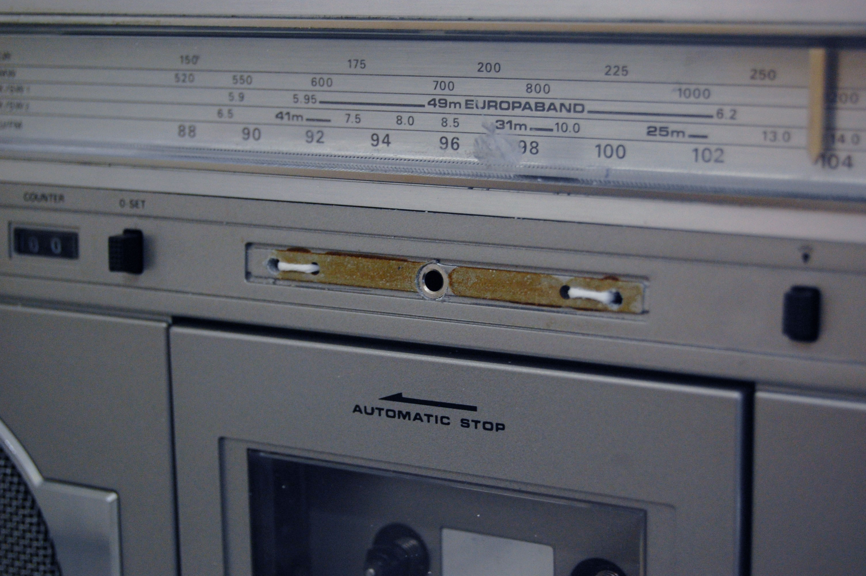
I don’t have a drill in my kit at the moment, so I had to improvise a bit. With the aid of a nail, screw, screwdriver, and pocket knife, I dug a relatively neat round hole to fit the socket in the front panel of the case. I had to scrape a bunch of plastic to make sure the socket wasn’t too deeply buried in the panel, otherwise no jack would click in there properly.
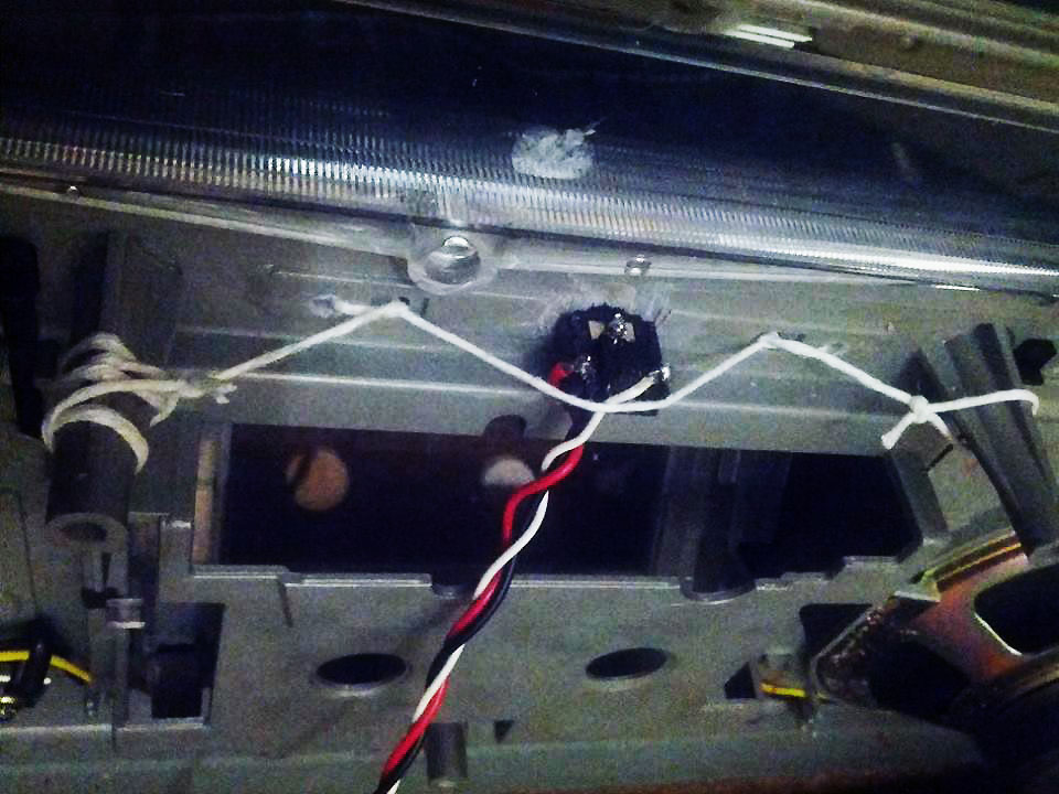
The next challenge was keeping it in place. The socket is pretty tightly stuck into the case, but not quite tight enough to withstand repeatedly plugging in an audio jack. I didn’t have any hot glue or super glue to keep it in place, so I fixed it up with a very taut piece of string that presses the socket to the panel. It appears to do the trick, as I haven’t managed to push the socket back once.
Putting everything back together involved a lot of pushing around things to make them fit in place, but overall I didn’t experience any major hurdles in that.
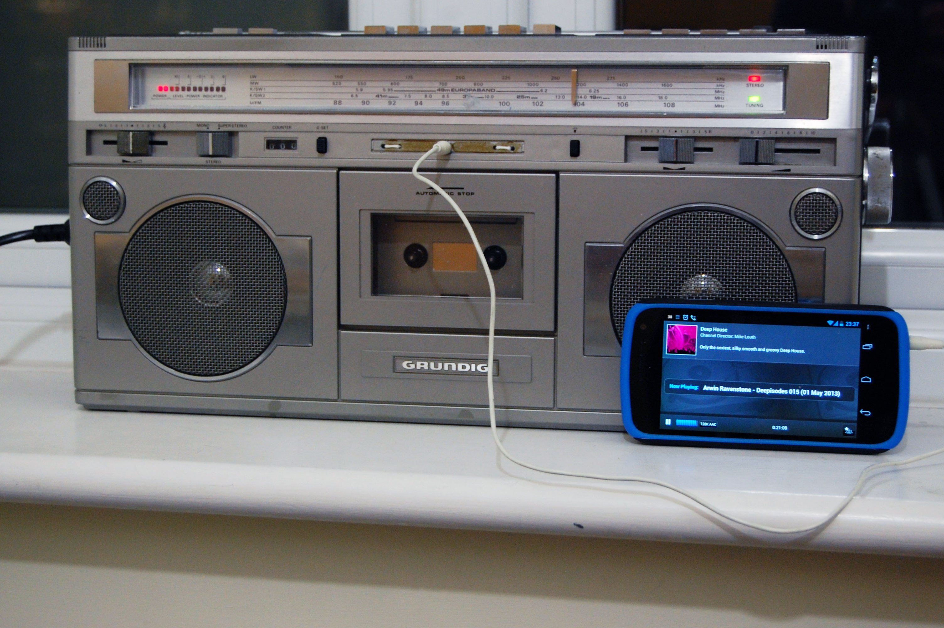
Works like a charm!
On a side note, I’d like to apologize for the terrible quality of some of the photographs. I took a few phone pictures throughout to show a friend, and those made it in here. I wasn’t focussed on getting good photography done, and only later decided to put together a write-up of the hack.